background image

Repair information

4-79


4048-1xx

7. Use a flat blade screwdriver to wedge the charge roll arm from 

the left guide assembly and remove the inner link.

Содержание T 430

Страница 1: ...ark and Lexmark with diamond design are trademarks of Lexmark International Inc registered in the United States and or other countries Table of contents Index Safety and notices Trademarks Start diagnostics Revised February 2005 ...

Страница 2: ...ucts programs or services do not imply that the manufacturer intends to make these available in all countries in which it operates Any reference to a product program or service is not intended to state or imply that only that product program or service may be used Any functionally equivalent product program or service that does not infringe any existing intellectual property right may be used inst...

Страница 3: ...lash memory 1 5 Printer data streams 1 5 Print area 1 6 Supplies 1 6 Fonts 1 6 Media and paper handling 1 7 Media 1 7 Standard and optional paper sources 1 8 Input media sources 1 9 Output media 1 10 Acronyms 1 11 Diagnostic information 2 1 Start 2 1 Power On Reset POR sequence 2 2 Symptom tables 2 3 POST symptom table 2 3 Printer symptom table 2 4 Messages and error codes 2 6 Service error codes ...

Страница 4: ...t quality service checks 2 50 Solving print quality problems 2 56 Diagnostic aids 3 1 Additional service menus 3 1 Diagnostics Mode 3 2 Entering Diagnostic Mode 3 2 REGISTRATION 3 4 PRINT TESTS 3 5 HARDWARE TESTS 3 6 DUPLEX TESTS 3 9 INPUT TRAY TESTS 3 12 BASE SENSOR TEST 3 14 DEVICE TESTS 3 14 PRINTER SETUP 3 15 EP SETUP 3 17 ERROR LOG 3 18 Configuration Menu 3 21 Entering CONFIG MENU 3 21 Maint ...

Страница 5: ...mbly removal 4 29 Fuser exit sensor removal 4 33 Cartridge contact assembly removal 4 34 Tray damper and spring removal 4 35 Door latch removal 4 36 Paper guide roller removal 4 37 Charge roll removal 4 38 Right guide removal 4 39 Left guide removal 4 40 Cartridge signature button sensor removal 4 42 Transfer roll assembly 4 43 Bracket paper detect input sensor removal 4 44 D roll feed removal tra...

Страница 6: ...ations 5 1 Connectors 5 2 Controller card assembly 5 2 Low voltage power supply LVPS 5 7 High voltage power supply HVPS 5 8 Preventive maintenance 6 1 Safety inspection guide 6 1 Lubrication specifications 6 1 Scheduled maintenance 6 2 Maintenance kits 6 2 Maintenance kit parts group 6 3 Parts catalog 7 1 How to use this parts catalog 7 1 Assembly 1 Covers 7 2 Assembly 2 Paper feed 7 4 Assembly 3 ...

Страница 7: ...Laser notices vii 4048 1xx Laser notices The following laser notice labels may be affixed to this printer as shown Laser advisory label ...

Страница 8: ...service condition Laser Der Drucker erfüllt gemäß amtlicher Bestätigung der USA die Anforderungen der Bestimmung DHHS Department of Health and Human Services 21 CFR Teil J für Laserprodukte der Klasse I 1 In anderen Ländern gilt der Drucker als Laserprodukt der Klasse I der die Anforderungen der IEC International Electrotechnical Commission 60825 1 gemäß amtlicher Bestätigung erfüllt Laserprodukte...

Страница 9: ... par l utilisateur ou de révision l exposition à des rayonnements laser supérieurs à des rayonnements de Classe I Avvertenze sui prodotti laser Questa stampante è certificata negli Stati Uniti per essere conforme ai requisiti del DHHS 21 CFR Sottocapitolo J per i prodotti laser di classe 1 ed è certificata negli altri Paesi come prodotto laser di classe 1 conforme ai requisiti della norma CEI 6082...

Страница 10: ... nivel de la Clase I durante su uso normal el mantenimiento realizado por el usuario o cualquier otra situación de servicio técnico Declaração sobre Laser A impressora está certificada nos E U A em conformidade com os requisitos da regulamentação DHHS 21 CFR Subcapítulo J para a Classe I 1 de produtos laser Em outros locais está certificada como um produto laser da Classe I em conformidade com os ...

Страница 11: ...ontworpen dat bij normaal gebruik bij onderhoud of reparatie conform de voorschriften nooit blootstelling mogelijk is aan laserstraling boven een niveau zoals voorgeschreven is voor klasse 1 Lasermeddelelse Printeren er godkendt som et Klasse I laserprodukt i overenstemmelse med kravene i IEC 60825 1 Klasse I laserprodukter betragtes ikke som farlige Printeren indeholder internt en Klasse IIIB 3b ...

Страница 12: ...ja suojalukitus ohitettaessa olet alttiina näkymättömälle lasersäteilylle Älä katso säteeseen VARNING Osynlig laserstrålning när denna del är öppnad och spärren är urkopplad Betrakta ej strålen Laser notis Denna skrivare är i USA certifierad att motsvara kraven i DHHS 21 CFR underparagraf J för laserprodukter av Klass I 1 I andra länder uppfyller skrivaren kraven för laserprodukter av Klass I enli...

Страница 13: ... foreskrevne serviceoperasjoner Avís sobre el Làser Segons ha estat certificat als Estats Units aquesta impressora compleix els requisits de DHHS 21 CFR apartat J pels productes làser de classe I 1 i segons ha estat certificat en altres llocs és un producte làser de classe I que compleix els requisits d IEC 60825 1 Els productes làser de classe I no es consideren perillosos Aquesta impressora cont...

Страница 14: ...xiv Service Manual 4048 1xx Japanese Laser Notice Chinese Laser Notice ...

Страница 15: ...Laser notices xv 4048 1xx Korean Laser Notice ...

Страница 16: ...xvi Service Manual 4048 1xx ...

Страница 17: ...g the product before you begin or use caution if the product must receive power in order to perform the task Consignes de sécurité La sécurité de ce produit repose sur des tests et des agréations portant sur sa conception d origine et sur des composants particuliers Le fabricant n assume aucune responsabilité concernant la sécurité en cas d utilisation de pièces de rechange non agréées Les consign...

Страница 18: ...otto deve essere alimentato per eseguire l intervento Sicherheitshinweise Die Sicherheit dieses Produkts basiert auf Tests und Zulassungen des ursprünglichen Modells und bestimmter Bauteile Bei Verwendung nicht genehmigter Ersatzteile wird vom Hersteller keine Verantwortung oder Haftung für die Sicherheit übernommen Die Wartungsinformationen für dieses Produkt sind ausschließlich für die Verwendun...

Страница 19: ...l equipo o tenga cuidado si para trabajar con él debe conectarlo Informações de Segurança A segurança deste produto baseia se em testes e aprovações do modelo original e de componentes específicos O fabricante não é responsável pela segunrança no caso de uso de peças de substituição não autorizadas As informações de segurança relativas a este produto destinam se a profissionais destes serviços e n...

Страница 20: ...ducte està orientada exclusivament a professionals i no està destinada a ningú que no ho sigui El risc de xoc elèctric i de danys personals pot augmentar durant el procés de desmuntatge i de servei d aquest producte El personal professional ha d estar ne assabentat i prendre les mesures convenients PRECAUCIÓ aquest símbol indica que el voltatge de la part de l equip amb la qual esteu treballant és...

Страница 21: ...Safety information xxi 4048 1xx ...

Страница 22: ...ides instructions for making printer adjustments and removing and installing FRUs 5 Locations and connections uses illustrations to identify the connector locations and test points on the printer 6 Preventive maintenance contains the lubrication specifications and recommendations to prevent problems 7 Parts catalog contains illustrations and part numbers for individual FRUs Definitions Note A note...

Страница 23: ... field replaceable unit FRU or part Use the error code charts symptom index and service checks to determine the symptom and repair the failure See Diagnostic information on page 2 1 for the location of each section See the Repair information on page 4 1 to help identify parts After completing the repair perform tests as needed to verify the repair Standard features Models 101 102 111 Duplex Parall...

Страница 24: ... inch shank Slotted screwdriver Small Phillips screwdriver Spring hook When taking voltage readings always use the printer frame as ground unless another ground is specified Printer identification Serial number Look for the serial number label on the inside front cover of the printer ...

Страница 25: ...General information 1 3 4048 1xx Printer features and specifications Operator panel The operator panel consists of a two line display and six buttons Menu is two buttons ...

Страница 26: ...int resolution The IET setting is selected when a print resolution is selected using the Quality Menu Toner saver and print darkness settings are set when a toner darkness is selected using the Quality Menu Print Quality setting All models Print resolution 300 dpi 600 dpi 1200 Image Quality 2400 Image Quality 1200 dpi Image Enhancement Technology IET 2 bits pel 4 bits pel Toner saver Print darknes...

Страница 27: ...er data streams Memory Models 101 and 111 102 Standard memory 32MB 64MB Standard flash memory None None Memory options 8MB DIMM 16MB DIMM 32MB DIMM 64MB DIMM 128MB DIMM 256MB DIMM Maximum of memory DIMM 1 1 Maximum possible memory 288MB 320MB Flash memory options 16MB 32MB Maximum of flash memory options 1 1 Maximum possible flash memory 32MB 32MB Indicates option is supported Data streams All mod...

Страница 28: ...r flash Print area option All models Normal Fit to page Edge to edge Print cartridge Average yield Approximate coverage Lexmark Return Program print cartridges 6 000 12 000 5 5 Regular cartridges without Lexmark Return Program terms and conditions 6 000 12 000 5 5 Fonts options All models PCL bitmapped 2 PCL scalable 89 PostScript scalable 91 PPDS bitmapped 5 PPDS scalable 39 ...

Страница 29: ...pported media media weights and media textures which together provide optimal print quality across a variety of media Note Indicates media is supported Media supported All models Paper Card stock Transparency Labels Envelope Bond Media weights Heavy Normal Light Media textures Rough Normal Smooth ...

Страница 30: ...n 1 1 Duplex standard in models 101 and 102 only Options Maximum of optional drawers 2 2 Optional drawers Note When two optional drawers are installed the first must be a 250 sheet drawer 250 sheet drawer 500 sheet drawer The 500 sheet drawer supports the following sizes A4 JIS B5 folio letter legal and executive Maximum number of media input sources 4 4 Maximum input sheet capacity excluding enve...

Страница 31: ...Multipurpose feeder Optional 250 sheet drawer Optional 500 sheet drawer Duplex models 101 102 only Letter 11 x 17 Legal A4 A3 A5 Folio Statement JIS B4 JIS B5 Executive Universal 7 3 4 envelope 9 envelope 10 envelope DL envelope C5 envelope B5 envelope Other envelope Size supported without size sensing ...

Страница 32: ...izes 150 sheet standard bin 20 sheet rear exit Letter A4 Legal 11 x 17 A3 Folio Statement A5 JIS B4 JIS B5 Executive Universal 7 3 4 envelope 9 envelope 10 envelope DL envelope C5 envelope B5 envelope Other envelope Size supported but results may be unacceptable ...

Страница 33: ...Supply IET Image Enhancement Technology KB Kilobyte LCD Liquid Crystal Display LSU Laser Scanning Unit LVPS Low Voltage Power Supply MPF Multipurpose Feeder NAND Not And Gate NVRAM Nonvolatile Random Access Memory PIN Personal Identification Number PJL Printer Job Language POR Power On Reset POST Power On Self Test PPDS Personal Printer Data Stream RAM Random Access Memory RIP Raster Image Process...

Страница 34: ...1 12 Service Manual 4048 1xx ...

Страница 35: ...action for a malfunctioning printer To determine the corrective action to repair a printer look for the following information Does the POR stop Check the Power On Reset POR sequence on page 2 2 POST symptom table on page 2 3 Do you have a symptom rather than an error message Check the Symptom tables on page 2 3 If you have an error message or user message check the following Service error codes on...

Страница 36: ...l across the operator panel 3 A screen is displayed with the memory and processor speed A typical example of this message is 4 Performing Self Test is displayed 5 Busy is displayed 6 Close Door will be posted if the cover is open 7 Any cartridge errors such as Defective Cartridge are posted 8 Applicable maintenance messages are posted For example 80 Scheduled Maintenance 9 Applicable toner low mes...

Страница 37: ...mpletes except display is incomplete or erratic See Operator panel service check on page 2 43 POST complete except display does not function See Operator panel service check on page 2 43 Main motor does not come on See Main motor service check on page 2 42 Fan does not come on See Cooling fan service check on page 2 36 Fuser heater does not come on See Cold fuser service check on page 2 41 Fuser h...

Страница 38: ...50 Black page See Black page on page 2 51 Heavy background See Heavy background on page 2 52 Light print See Light print on page 2 54 White or black lines or bands See White or black lines or bands on page 2 54 Toner on back of page See Toner on back of page on page 2 55 Paper jams See Paper feed service checks on page 2 45 Main motor noisy or does not move See Main motor service check on page 2 4...

Страница 39: ...les stacks poorly or curls on page 2 49 Top cover will not close See Cover interlock switch service check on page 2 37 Operator panel button does not respond See Operator panel service check on page 2 43 or Controller card service check on page 2 38 Operator panel light does not light or is very dim See Controller card service check on page 2 38 Symptom Action ...

Страница 40: ...the rear door and fuser while observing the DC motor If the torque is too high isolate the problem to the redrive and repair or replace as necessary If the torque seems normal check the cabling for continuity and replace the motor with cabling 911 DC exit motor 912 DC exit motor below speed 913 DC exit motor over speed 914 DC pick motor no encoder feedback Verify motor is plugged into controller c...

Страница 41: ... faulty printhead 932 Printhead lost hsyncs Replace the printhead 934 Mirror motor lost lock Replace the printhead 935 Mirror motor unable to reach operating speed Faulty printhead cabling or connector 936 Transport motor initial lock failure Indicates a problem with the main drive motor or a jam occurred during the motor ramp up to speed 937 Transport motor lost lock Faulty motor or a jam occurre...

Страница 42: ... pin 6 and 5 of the tray If the resistance is less than 50 ohms replace the drawer 950 Controller card There is a mismatch between the variables in the EPROM on the operator panel card and those in the secure NVRAM on the controller card This can only occur after a replacement of one of the two parts and the replaced part is faulty Replace the controller card or the operator panel Warning Always r...

Страница 43: ...ction code can reflash NAND If this does not fix the problem replace the controller card 959 SRAM failure Error codes 956 957 and 959 are controller card failures Perform a power on reset POR If this does not fix the problem replace the controller card 960 RAM soldered on the card is bad Indicates a DRAM Memory Error on the controller card Replace the controller card 961 RAM in slot 1 is bad If an...

Страница 44: ... port A failure with the network port If the printer is a network model replace the controller card See Controller card assembly removal on page 4 50 976 Software error in network port 978 Bad checksum while programming network port 979 Flash parts failed while programming network port 980 device Comm The engine is experiencing unreliable communications to the specified device Service errors 980 t...

Страница 45: ...om types which has been named by the user then only the custom type name is displayed on line 2 The name may be truncated to fit the display Change input source custom string This message displays when the user should change the media installed in one of the input options input source Tray 1 Tray 2 Tray 3 or MP feeder custom string a user definable name Change input source size This message displa...

Страница 46: ... been removed from the printer possibly to clear a paper jam or to uninstall the option The option may be attached to the printer but a communications problem may prevent the printer from detecting the option For example there may be a poor connection or a hardware failure The following actions may be taken If the option was temporarily removed or not connected properly reattach or reconnect it Pr...

Страница 47: ...ress Go Note This situation usually occurs when the tray is refilled during a job To refill a tray during a printing session press Stop and wait for pages to reach the output bin before refilling the tray The following actions may be taken Insert the requested tray Press Menu until Busy Waiting displays The following selections are available Cancel Job Reset Printer If the message cannot be cleare...

Страница 48: ...the controller card Load input source custom type name Input source Tray 1 Tray 2 Tray 3 or MP Feeder Custom type name is a user defined media type The following actions may be taken Load media in the indicated source Press Menu until Busy Waiting displays Select one of the following Cancel Job Reset Printer If the message cannot be cleared go to Input tray s service check on page 2 64 Load input ...

Страница 49: ...tial Print job and there are no jobs associated with the PIN number The following actions may be taken Press Go to enter another PIN Press Return or Stop to exit the PIN entry operation Res Reduced warning This message displays only when the Resolution Reduction setting is enabled The following actions may be taken Press Stop to take the printer offline No more data is processed but the printer pr...

Страница 50: ...o short to print the formatted data This occurs when the printer does not know the actual paper size loaded in the tray Make sure the Paper Size setting is correct for the size paper that is being used The following actions may be taken Press Go to clear the message and continue printing Press Menu until Busy Waiting displays Select one of the following Cancel Job Reset Printer 35 Res Save Off Def...

Страница 51: ...lear the message Press Menu until Busy Waiting appears The following actions are available Cancel Job Reset Printer 37 Insufficient Defrag Memory This message displays when the printer memory is fragmented Defragmentation is required and additional memory is required to complete the task Press Go to clear the message Defragmentation will not continue and no changes are made to memory and no resour...

Страница 52: ...ction Reset Printer may be available 38 Memory Full This message displays when the printer is processing an incoming job and there is insufficient memory available to continue processing the job The following actions may be taken Press Go to clear the message Perform the defragment operation Simplify the print job Delete fonts macros and other data in RAM Install additional memory Press Menu to di...

Страница 53: ...y be taken Press Go to clear the message and continue processing the job Press Menu until Busy Waiting appears The following are available Cancel Job Reset Printer 51 Defective Flash This message displays when the printer detects a defective flash This error may occur at power on or during flash format and write operations Press Go to clear the message The flash is marked as bad and normal operati...

Страница 54: ...rallel port but the parallel port has been disabled Once this message is displayed reporting of further errors is suppressed until the menus are entered or the printer is reset The following actions may be taken Press Go to clear the message The printer discards any data received on the parallel port Press Menu until Busy Waiting appears and select Reset Printer 56 Standard USB Port Disabled Displ...

Страница 55: ...l an associated compatible option or hot unplug the option 80 Scheduled Maintenance Replace the fuser assembly transfer roller charge roll and pick rolls at this recommended interval to maintain the print quality and reliability of the printer The parts are available as a maintenance kit For more information see Scheduled maintenance on page 6 2 81 Engine Code CRC Failure This error displays when ...

Страница 56: ...o be covered Remove the print cartridge and open the rear door to remove the media 201 Paper Jam Remove Cartridge Paper is jammed between the printer input and exit sensor Remove the print cartridge to clear the paper path 202 Paper Jam Open Rear Door The exit sensor is either covered during POR or covered too long Open the rear door to access the jam area 231 Paper Jam Remove Tray1 Pull Down Leve...

Страница 57: ...forces in the redrive unit rear cover or a worn motor loc can be Front or Rear 242 Paper Jam Check Tray 2 Tray 2 pass thru sensor is covered during warm up Try opening Tray 2 If the tray is difficult to remove then you may have to remove the tray above or below the tray to remove the jammed pages 243 Paper Jam Check Tray 3 Media picked from tray 3 made it through the tray 2 pass thru sensor but fa...

Страница 58: ...d problems in the base printer To identify the bytes Displayed error codes When a 9xx or 2xx error displays 1 Press and hold Return and press Select to enter for sub error codes The first screen of information displays Write down the information 2 Continue pressing Return and Select until each screen of information is obtained When the last screen displays the original message displays Printed err...

Страница 59: ...variables are listed below media source 10 Multipurpose tray MPT 11 Tray 1 12 Tray 2 13 Tray 3 80 Duplex unit media size 1 Letter 2 Legal 3 B5 4 A4 5 Executive 6 A5 7 Custom size 9 7 in envelope A 9 Envelope B 10 Envelope C 8 661 in Envelope D C5 Envelope E B5 Envelope F Legal envelope ...

Страница 60: ... of the transfer roll and input to the fuser for anything that might cause the paper to remain over the input sensor 200 84 xx 01 x1 The video signal never started within 2 inches after actuating the input sensor Check input sensor and flag x1 media size 200 84 xx 02 x1 x2 Paper is over the input sensor too long x1 media size x2 source Possible causes are Multi sheet feeding Paper size is not the ...

Страница 61: ...sor 200 84 xx 0F x1 x2 x3 The option tray pass thru sensor was never deactivated x1 media size x2 media source and x3 media source where paper jam was detected Check the pass thru sensor and flag for correct operation Check to see if paper has cleared the pass thru area of the option where the paper jam occurred 243 84 xx 18 There is media over the Tray 2 pass thru sensor during warm up If no medi...

Страница 62: ...x3 trailing edge state Possible causes Slow or missing main motor positional feedback Paper too fast to input sensor Gap too small on interpage servo 200 84 xx 26 This code indicates that media has activated the input sensor however the printhead fell out of lock condition or expected a stable lock too soon The media may have also reached the input sensor early 200 84 xx 2F x1 x2 x3 Laser servo ne...

Страница 63: ...sible cause is multiple sheets picked 200 84 00 10 The main motor driver failed to detect a specific motor after two tries Possible causes for this error are The main drive motor has stalled An incorrect main drive motor gearbox assembly has been installed 200 84 00 31 00 00 00 Trailing edge never cleared input sensor when feeding out media that was detected during warm up Clear the media or debri...

Страница 64: ...an be caused by a broken fuser exit sensor flag This may also be caused by erratic operation of exit sensor flag or exit sensor or a defective piece of media 202 89 xx 04 x1 The fuser exit sensor never actuated from the sheet going through the fuser before the next page begins feeding x1 media size 202 89 xx 0D The fuser exit sensor bounced Check the exit sensor for correct operation Check the sen...

Страница 65: ...er card 201 8D 00 01 00 00 00 User pressed Go or Continue after an 8D xx 00 jam but never opened the top cover Need to open cover and clear any media under cartridge before continuing 201 8D 00 02 00 00 00 Exit sensor never made by leading edge of paper when feeding out media that was detected during warm up 201 8D x1 03 x2 x3 x4 Page arrived at fuser too soon and feed time was too quick Possibly ...

Страница 66: ...edia source 250 8E xx 09 x1 The second pick from the MPF or Tray 1 failed When other sheets were committed to the paper path x1 media source 250 8E 00 0D x1 00 00 Paper reached the input sensor after engine timed out and was feeding the paper ahead to the output tray x1 media source 200 8E x1 11 x2 x3 x4 Took too long to ramp up DC redrive motor 239 8E 00 15 x1 00 x2 Excessive PWM for the DC redri...

Страница 67: ...not expected paper in duplex during warm up 238 8F xx 02 x1 x2 00 Duplex sensor never changed state when sheet left duplex possible sticky sensor x1 x2 timeout value 235 Sub error codes continued First 6 bytes sub error code data xx can be any value Explanation Possible error message ...

Страница 68: ...age power supply No backlight no text on operator panel and 5 beeps POST J5 OP PANEL operator panel Go to Dead machine service check on page 2 39 second note 914 POST J6 EXIT MOTOR redrive motor 917 POST J19 HVPS high voltage power supply and fan 924 POST J18 THERM thermistor and smart chip 929 Print multiple pages J12 MPF SENSOR multipurpose feeder sensor and toner sensor 931 POST J3 LSU laser pr...

Страница 69: ...LEX input sensor narrow media sensor and duplex sensor Remove Paper Standard Bin POST J16 EXIT exit sensor and bin full sensor Option tray is not available Attempt to select option tray in PAPER SOURCE menu J21 TRAY option tray Error or message if cable is unplugged Condition required to obtain error Check connection at Connector name and description ...

Страница 70: ...nd socket 5 at 5 V dc Cooling fan service check FRU Action Cooling fan fuser Cooling fan LVPS Make sure the plugs of the cooling fan cables are properly seated Both fans are connected to the same 24 V dc on pin 1 at J19 on the controller Pin 2 is ground for both fans Therefore if one fan functions and the other does not either the fan or the cable is faulty Turn the printer off and disconnect the ...

Страница 71: ...ck switch Push the cover interlock switch to the closed position and verify continuity between the bottom and middle terminals Open the switch and verify continuity between the bottom and top terminals The top and middle terminals should indicate discontinuity at all times If the switch is good verify 5 V dc on the middle spade of the cable and ground on the top spade of the cable If voltage is no...

Страница 72: ...OST within approximately 12 15 seconds in the following sequence a The operator panel light comes on b Diamonds display from left to right c Dots display left to right d The memory size and processing speed temporarily display e The operator panel displays Performing Self Test f Ready displays If immediately following power on the operator panel lights are on but the printer does not go through st...

Страница 73: ...rify pins 2 5 and 6 are ground Replug the power cord and turn the printer on CAUTION Be careful to not ground pins to cage while testing Verify pin 4 is 5 V dc Verify pins 7 and 8 are 24 V dc If any one of these is incorrect replace the LVPS If these are correct check the controller card operator panel and wiring Note A dead machine implies no power beyond the LVPS If the printer behaves dead but ...

Страница 74: ...e photoconductor DC Check as follows 1 Turn printer off 2 Remove the right side cover See Right side cover removal on page 4 12 for more information 3 Remove the print cartridge 4 Check from C on the HVPS to the bearing on the left side of the charge roll See page 5 8 for more information 5 Check from the Dr B TAR developer roll D transfer roll T and photoconductor DC respectively to the correspon...

Страница 75: ...place the LVPS Make sure the fuser thermistor is correctly connected to the controller card J18 Fuser assembly If the fuser heater comes on and a fuser failure error code displays be sure the thermistor is firmly seated in connector J18 on the controller card assembly The thermistor cable goes through the frame by way of a connector Unplug the printer and disconnect the thermistor cable from the c...

Страница 76: ... If continuity exists on each wire replace the main motor If continuity does not exist on one or more of the wires replace the motor cable If the voltage is not correct verify 24 V dc on pins 1 and 2 on J17 If voltage is correct replace the controller card If the voltage is not correct check the LVPS Note Always check printhead alignment after replacing the controller card assembly See Printhead a...

Страница 77: ...card Verify pin 4 is ground Turn the printer on and verify 5 V dc on pins 2 and 5 Also verify 3 3 V dc on pins 6 and 7 If any of the voltages fail replace the controller card See Controller card assembly removal on page 4 50 If all of the voltages are correct verify the continuity of the operator panel cable If the cable fails continuity replace it See Operator panel cable removal on page 4 20 Oth...

Страница 78: ...lying even pressure to the PC drum The roll should rotate evenly and smoothly Replace the transfer roll assembly if the springs or bearings indicate damage or lack of proper function Inspect the transfer roll for signs of wear damage or contamination Replace the assembly as necessary Note Do not vacuum the roll Note Always check the bottom margin following a transfer roll replacement See REGISTRAT...

Страница 79: ...gear movement in the reference feed assembly located in the paper path below the cartridge If the gear motion cannot be stopped look for obstructions in the paper path such as debris or damage If the gear motion can be stopped while continuing to rotate the drive motor one of the following units has to be replaced Check or replace the FRUs in the following order Backup roller assemblies Reference ...

Страница 80: ...input sensor under the cartridge and the exit sensor at the fuser A 202 indicates a jam in the rear door Errors 231 235 237 and 238 indicate jams in the duplex If the printer functions correctly in the simplex but posts these errors in duplex check the sensor cable for continuity and replace the cable or sensor s as necessary FRU Action Paper feed assembly Paper feed solenoid Check the pick mechan...

Страница 81: ...r Make sure the cable is seated on the controller card assembly J20 Verify 5 V dc on pins 1 4 7 and ground on pins 3 6 and 9 See Locations and connections on page 5 1 for more information If correct replace the input paper feed sensor If the voltage is not correct replace the controller card assembly Note Always check printhead alignment after replacing the controller card assembly See Printhead a...

Страница 82: ...ally If this is true and the resistance is correct replace the controller card assembly Note Always check printhead alignment after replacing the controller card assembly See Printhead assembly adjustment on page 4 2 for hardware alignment of the printhead FRU Action Paper feed roll Paper feed assembly Check the paper feed roll D roll or pick roll for wear Verify that the extension spring is worki...

Страница 83: ...this setting a Select PARALLEL MENU from the Ready Menu b Select Parallel Mode 2 Selections are On and Off 6 If the printer fails to print on command from the host verify the following a Internal print test page prints correctly b The user application printer driver is set up correctly c The host computer has been restarted d The bidirectional parallel cable is connected correctly and is functiona...

Страница 84: ... card See Controller card assembly removal on page 4 50 If the voltages are correct check the printhead cable for continuity If the cable has continuity replace the printhead See Printhead removal on page 4 46 If the cable does not have continuity replace the cable With the cartridge removed and the printer off check continuity between HVPS DC designation on outer side of card and the PC pin insid...

Страница 85: ...f continuity fails replace the left guide assembly which includes this cable Check continuity from the charge roll left side bushing to the right side shaft If continuity fails remove the charge roll and clean the left side shaft and bushing See High voltage power supply HVPS on page 5 8 and check that the voltage measurements are 24 V dc on socket 4 and 5 V dc on socket 7 on the HVPS The pins soc...

Страница 86: ...t installation and contamination where contact is made with the print cartridge and HVPS card Clean as necessary If this does not correct the problem replace the HVPS If that does not correct the problem replace the controller card assembly Note Always check printhead alignment after replacing the controller card assembly See Printhead assembly adjustment on page 4 2 for hardware alignment of the ...

Страница 87: ...springs and bearings at both ends of the transfer roller The bearing assemblies should support the transfer roller applying even pressure to the PC drum Replace the transfer roll assembly if either spring shows signs of damage or fatigue See Transfer roll assembly on page 4 43 Inspect the transfer roller for signs of wear or damage and replace if necessary Note Cleaning or vacuuming the transfer r...

Страница 88: ... all components appear free of contamination replace the following FRUs one at a time in the order shown Transfer roller Note Always check the bottom margin following a transfer roll replacement See REGISTRATION on page 3 4 Cartridge contact assembly HVPS card FRU Action Print cartridge Paper feed drive gears Banding appears as light or dark horizontal lines on a uniformly gray page or on a page w...

Страница 89: ... up on the belt edges This buildup may transfer to the backup roller later transferring to the back of the paper Inspect the belt and backup roller for signs of contamination and replace fuser assembly as necessary Transfer roller A transfer roller contaminated with toner can cause toner to transfer to the back of printed pages Inspect the transfer roller for contamination and replace as necessary...

Страница 90: ...he Print Quality Pages can also be printed from the Configuration Menu See Prt Quality Pgs on page 3 23 Problem Action Light or blurred characters The print cartridge may be getting low on toner To use the remaining toner remove the cartridge and shake the cartridge back and forth Reinstall the cartridge and press Go Change the Toner Darkness setting to a value greater than 8 Make sure you are usi...

Страница 91: ... marks may indicate which component is causing the problem 46mm Developer roll charge roll transfer roll 79 8mm Fuser belt 80 5mm Fuser backup roll 95mm Photo conductor Inspect the component if possible for debris or damage Repalce the component or tone cartridge as necessary Faint images or repetitive spots appear on the page Select a different media type or form type setting from your printer dr...

Страница 92: ...it from side to side to redistribute the toner Replace the cartridge The Toner Low message appears Remove the print cartridge and gently shake it from side to side to redistribute the toner Replace the cartridge Solid black areas on transparencies or paper contains white streaks Choose a different fill pattern in your software application Try a different type of paper Paper designed for copiers gi...

Страница 93: ...r from tray 1 and fan the paper Make sure tray 1 is selected from the printer driver Do not overfill the tray The paper fails to feed from the optional tray 2 or tray 3 Make sure the printer recognizes the optional trays POR the printer and check the cables Make sure the optional tray 2 is selected from the printer driver Remove the paper from the optional tray 2 and fan the paper Make sure the tr...

Страница 94: ...idge is installed properly Unexpected characters print or characters are missing Make sure you are using the correct printer driver Select hex trace mode to determine what the problem is To turn on hex trace 1 Select UTILITIES MENU from the READY MENU 2 Select Hex Trace To exit Hex Trace select Reset Printer from the JOB MENU or turn the printer off Restore factory defaults See Factory Defaults on...

Страница 95: ... displays The Diagnostics Mode group contains the settings and operations used while manufacturing and servicing the printer See Diagnostics Mode on page 3 2 for more information Configuration Menu 1 Press and hold Select and Return 2 Turn on the printer 3 Release the buttons whenPerforming Self Test displays The Configuration Menu group contains a set of menus settings and operations which are in...

Страница 96: ...erforming Self Test displays on the operator panel The tests are displayed on the operator panel in the order shown REGISTRATION PRINT TESTS Tray 1 Tray 2 displays only if installed Tray 3 displays only if installed MP Feeder Prt Quality Pages HARDWARE TESTS LCD Test Button Test DRAM Test Parallel Wrap displays in some configurations DUPLEX TESTS Quick Test Top Margin Sensor Test Duplex Feed 1 INP...

Страница 97: ... Serial Number Engine Setting 1 Engine Setting 2 Engine Setting 3 Engine Setting 4 Model Name Configuration ID Edge to Edge Par S Strobe Adj EP SETUP EP Defaults Fuser Temp Transfer Print Contrast Charge Roll Gap Adjust ERROR LOG Display Log Print Log Clear Log Select Exit Diagnostics to exit the Diagnostics Mode and return to normal mode ...

Страница 98: ...int the Quick Test page Press Go to print the test page While printing Quick Test Printing displays Once the Quick Test page completes printing the registration screen displays again 4 To exit press Return 5 Test the setting by printing the Quick Test page for all the source see PRINT TESTS on page 3 5 Select all the available sources To test the Duplex sources see DUPLEX TESTS on page 3 9 Print t...

Страница 99: ...Diagnostics Mode 2 Select the input source from the sources displayed on the Feed Test menu All installed sources are listed 3 Select either Single feeds one sheet of blank media from the selected source or Continuous continues feeding blank media from the selected source until Return or Stop is pressed 4 Press Return or Stop to exit the test Menu selections Description Tray 1 Standard tray Tray 2...

Страница 100: ...last page is blank The Print Quality pages can also be printed from the Configuration Menu HARDWARE TESTS LCD Test 1 Select LCD Test from Diagnostics Mode The LCD test continually executes the LCD display test 2 Press Return or Stop to cancel the test Button Test 1 Select Button Test from Diagnostics Mode With no buttons pressed several occurrences of OP Open appear on the display 2 To test the pr...

Страница 101: ...umber of times the memory test has passed and finished successfully Initially 000000 displays with the maximum pass count being 999 999 F represents the number of times the memory test has failed and finished with errors Initially 00000 displays with the maximum fail count being 99 999 2 Once the maximum pass count or fail count is reached the test stops the power indicator is turned on solid and ...

Страница 102: ...he number of times the memory test has passed and finished successfully Initially 000000 displays with the maximum pass count being 999 999 F represents the number of times the memory test has failed and finished with errors Initially 00000 displays with the maximum fail count being 99 999 5 Each time the test finishes the screen updates If the test passes the pass count increases by 1 however if ...

Страница 103: ...ex sheet to the front make sure you adjust the Top Margin for a single sheet See REGISTRATION on page 3 4 Use either letter or A4 paper to run the test If wider or narrower paper is used media width appears with either W for wide or N for narrow paper To run the Duplex Quick Test 1 Select Duplex Tests from Diagnostics Mode 2 Select Quick Test DMA Count Error DMA Address Error DMA Interrupt Error D...

Страница 104: ...Return or Stop to exit the test Top Margin Print the duplex Quick Test to verify the margin on the backside of the duplex page aligns with the front side See Quick Test on page 3 9 Since this test aligns against the front page make sure the front page is aligned the front side of a duplex page is facedown in the output bin See REGISTRATION on page 3 4 The Duplex Top Margin offset range is 16 to 16...

Страница 105: ...x input sensor in the duplex unit 3 Press Return or Stop to exit the test Duplex Feed 1 This test feeds a blank sheet of paper to the duplex paper stop position 1 To run the Duplex Feed 1 Test 1 Select Duplex Feed 1 from the Duplex Test menu The power indicator blinks while the paper is feeding 2 When the paper reaches the duplex paper stop position 1 the power indicator turns on solid and a messa...

Страница 106: ...1 Open the MPF door Note Do not open the front cover 2 Select the Feed Test from the Input Tray Test menu 3 Select the input source Only installed sources display but may include Tray 1 Tray 2 Tray 3 MP Feeder 4 Select Single to feed a single blank sheet or Continuous to feed blank sheets until you press Return or Stop The selected input source appears on the display Sensor Test This test is used ...

Страница 107: ...es the sensor is closed Not all sources have the same set of sensors The table below indicates which sources should display which sensors 4 Press Return or Stop to exit the test Tray 2 TP OP P OP Source Tray present TP Pass thru sensor P Tray 1 Yes1 No Tray 2 Yes2 Yes3 Tray 3 No Yes3 Multipurpose feeder Yes No 1 Only available when tray 2 is installed 2 Only available when tray 3 is installed 3 On...

Страница 108: ...oor sensor The selected sensor is displayed with OP for open or CL for closed You can actuate the sensors to toggle between open and closed DEVICE TESTS This menu is only displayed if flash memory is installed Flash Test This test causes the file system to write and read data on the flash to test the flash Warning This test destroys all data on the flash The flash will be unformatted at the end of...

Страница 109: ...g affects the following defaults Warning Changing the Defaults setting causes the printer to reset the printer NVRAM to factory settings Flash Test Testing Printer setting U S value Non U S value Default paper size Letter A4 Envelope size 10 Envelope DL Envelope Fax paper size Letter A4 PCL Symbol Set PC 8 PC 850 PPDS code page 437 850 Units of measure Inches Millimeters Where input sources do not...

Страница 110: ...ayed Configuration ID The configuration ID is used to communicate characteristics of certain areas of the printer that cannot be determined by hardware sensors The configuration ID was originally set when the printer is manufactured and is located on the printer label Edge to Edge When Edge to Edge is set to On text and graphics are printed with all margins set to the physical edges of the page Th...

Страница 111: ...efault Lower and Lowest Transfer Selections are Low Medium default and High Print Contrast Selections are Low Medium default and High Charge Roll Selections are Low Medium default and High Gap Adjust Adjusts the minimum gap between sheets during printing This setting reduces speed pages per minute but can be used to reduce curl of printed media and improve stacking in the output bin Range is 0 def...

Страница 112: ...r is discarded Identical errors in consecutive positions in the log are entered All 2xx and 9xx error messages are stored in the error log To view the error log 1 Select Display Log from the Error Log menu The error log is displayed on three screens but only four entries are shown at a time To move to the next screen press Menu For example In this example the last error was a 200 error In position...

Страница 113: ... log can be faxed to Lexmark or your next level of support for verification or diagnosis This report can also be printed from the Configuration Menu Because you can clear error logs the contents of this log may not match the contents when you view the error log To print the error log 1 Select Print Log from the Error Log menu 2 Press Return to exit the Error Log menu Model and Serial number Printe...

Страница 114: ... Log menu 2 Press Yes to confirm Select No to exit without clearing the log 3 Press Return to exit the Clear Log menu after clearing the log Exit Diagnostics Select Exit Diagnostics to exit the Diagnostic Mode and return to normal mode Clear Log Yes 1 000 2 000 3 000 4 000 ...

Страница 115: ...rforming Self Test displays on the operator panel The menu items appear on the operator panel in the order shown Maint Cnt Value Reset Maint Cnt Prt Quality Pgs Panel Menus PPDS Emulation Download Emuls Demo Mode Factory Defaults Energy Conserve ERROR LOG Paper Prompts Env Prompts Reduced Curl Exit Config Menu Select Exit Config Menu to exit the Configuration Menu and return to normal mode ...

Страница 116: ... determined by page count Select Maint Cnt Value from the CONFIG MENU Press Return to exit Reset Maint Cnt When 80 Scheduled Maintenance appears and the maintenance kit is installed see Scheduled maintenance on page 6 2 this number should be reset To reset the counter 1 Select Reset Maint Cnt from the CONFIG MENU 2 Press Select to reset the counter to zero Press Return to cancel Maint Cnt Value 12...

Страница 117: ...es can also be printed from the Diagnostics Mode Panel Menus If no password is set Panel Menus lets you restrict access to the Ready Menu Group When a password is set by an administrator this menu item does not appear 1 Select Panel Menus from the Diagnostics Mode 2 Select Disable to make menus in the Ready Menu Group inaccessible To change the setting select Panel Menus and select Enable to make ...

Страница 118: ...ate downloaded emulations restart the printer Demo Mode This menu item lets you turn demo mode on or off 1 Select Demo Mode from CONFIG MENU 2 Select Activate to turn the demo mode on or Deactivate to turn demo mode off Factory Defaults This menu lets you restore the printer settings to their factory default values 1 Select Factory Defaults from the Configuration Menu 2 Select either Restore Base ...

Страница 119: ... menu Disable lets you enable or disable Power Saver from the customer menu ERROR LOG See ERROR LOG on page 3 18 for a more detailed description The error log printed from the Diagnostics Mode contains additional debug information for 9xx errors than the error log printed from the Configuration Menu You can also view or clear the log from the Diagnostics Mode ...

Страница 120: ... Log from the Error Log menu 2 Press Return to exit the Error Log menu Paper Prompts Setting Paper Prompts controls which tray a change prompt is directed to when paper is sensed to be the wrong size Selections include Auto MP Feeder and Manual Paper Env Prompts Setting Env Prompts controls which tray a change prompt is directed to when envelopes are sensed to be the wrong size Selections include ...

Страница 121: ...nt media from the entire paper path The following illustration shows the path that print media travels through the printer The path varies depending on the input source trays and multipurpose feeder and output bin you are using See Paper jam messages on page 2 22 for more information Note To avoid tearing print media pull all jams out gently and slowly Use both hands and even pressure if possible ...

Страница 122: ...3 28 Service Manual 4048 1xx ...

Страница 123: ...ctricity in your body to the printer Hold the ESD sensitive part by its edge connector shroud cover do not touch its pins If you are removing a pluggable module use the correct tool Do not place the ESD sensitive part on the printer cover or on a metal table if you need to put down the ESD sensitive part for any reason first put it into its special bag Machine covers and metal tables are electrica...

Страница 124: ...e misaligned The entire image is rotated relative to the print media edges However a misaligned printhead causes the horizontal lines to appear skewed while the vertical lines remain parallel to the vertical edges To align the printhead 1 Enter the Diagnostic Menu See Entering Diagnostic Mode on page 3 2 and print the Quick Test To print the test a Select Print Tests from the Diagnostic Menu b Sel...

Страница 125: ... so that the left side top edge aligns with the right side top edge 4 If the grid lines of the paper on the right side extend below the grid lines of the left side adjust the printhead clockwise relative to the printer and recheck See the left side of the figure below Adjust the printhead counterclockwise if the left side grid lines extend below the right side See the right side of the figure belo...

Страница 126: ...thead if necessary adjust registration of the left right top and bottom margins See REGISTRATION on page 3 4 Note Printhead misalignment results in skewed horizontal lines but a consistent margin top to bottom of page Paper feed misalignment results in entire image rotated on the paper See Adjusting paper feed alignment skew on page 4 5 ...

Страница 127: ...ed through the hole in the main drive assembly It is between the controller card cage and the main motor board Adjust the screw counterclockwise which rotates paper counterclockwise in the printer path image clockwise and vice versa Verify alignment by printing the Quick Test page 1 Enter the Diagnostic Menu See Entering Diagnostic Mode on page 3 2 2 Select Print Tests from the Diagnostic Menu 3 S...

Страница 128: ... or less at each location and then rotate the gears or mechanism to evenly distribute the lubricant Use Nyogel 744 P N 99A0394 or IBM 23 P N 99A0462 Note Be careful to not spread the grease to other parts of the printer P N 56P23637 Ratchet drive Lubricate the teeth of all the gears in the drive assembly except the indicated gear P N 56P2326 Drive assembly Lubricate all gears except this one ...

Страница 129: ...eassembling the printer The printer may not detect a disconnected sensor in some areas without extensive running Note Always print a page from each paper source to verify reassembly P N 56P2359 MPF pick roll assembly P N 56P2302 Rear cover assembly P N 56P2327 Exit gear drive assembly ...

Страница 130: ...paper tray before you perform removal procedures Unless otherwise stated reinstallations are in reverse order of removal MPF door cover removal 1 Remove the tray 2 Open the front cover 3 Open the MPF door to where the latches are just clear of the printer about 15 4 Lift the left side of the cover to release it from the hinge 5 Move the cover to the left to separate the right pivot ...

Страница 131: ...Repair information 4 9 4048 1xx Front cover removal 1 Open the front cover 2 Remove the two screws holding the front cover to the hinge arm A 3 Unlatch the ends of the hinge arms ...

Страница 132: ...panel cable cover and remove the cable cover 5 Disconnect the operator panel cable C from the operator panel 6 Remove the front cover with the operator panel attached If replacing the front cover remove the operator panel See Operator panel assembly removal on page 4 22 ...

Страница 133: ... 2 Remove the two screws as shown A 3 Remove the E clips from both hinges that connect the left and right guides to the top cover B 4 Remove the stud hinges 5 Open the rear exit door 6 Remove the two screws as shown C 7 Remove the top cover being careful not to damage the output tray full flags when you remove the cover ...

Страница 134: ...ay 2 Open the front cover 3 Open the MPF door 4 Remove the screw below the front cover which fastens the side cover to the frame A 5 Open the rear cover and remove the second screw down from the top left corner B 6 Pull the top of the right cover away from the printer slightly ...

Страница 135: ...Repair information 4 13 4048 1xx 7 Unlatch the cover from the frame behind the front of tray C 8 Remove the cover The MPF door may need to be lifted slightly for the side cover to clear ...

Страница 136: ...4 14 Service Manual 4048 1xx Left side cover removal 1 Open the front cover and the MPF door 2 Disengage the two latches A located in the front and top 3 Swing the left side cover away from the printer ...

Страница 137: ...ver removal on page 4 12 3 Remove the left side cover See Left side cover removal on page 4 14 4 Disconnect the sensor cable in line connector A below the lower left corner of the controller cage Note Be sure to reconnect the sensor cable when reinstalling the rear cover The printer fails to operate without this connection ...

Страница 138: ...ightly with one hand while pulling out on the rear cover Installation notes Handle carefully Do not touch the rollers When reinstalling the rear cover position the fuser exit guide fingers so they are not bound by the rear cover A bind causes jams Be sure the spring contacts on the left side of the rear cover make good contact with the LVPS cage ...

Страница 139: ...Open the rear exit door 2 Use your index finger or flatblade screwdriver to disengage the left facing the back of printer hinge A from the rear cover 3 Swing the left side out to clear the printer and then move the door to the left to disengage the right hinge ...

Страница 140: ...Open the front cover 2 Remove the two screws A holding the front top cover 3 Remove the two screws B from the rear 4 Lift the rear part of the top cover to clear the output tray full flags You do not have to disconnect the top cover from the left and right guides ...

Страница 141: ...Repair information 4 19 4048 1xx 5 Press the side of the flag to unclip the flag from the frame 6 Repeat to remove the other flag ...

Страница 142: ...on page 4 14 2 Remove the inner shield A 3 Loosen the five screws B slide the controller card cage cover toward the rear and remove 4 Disconnect the cable from the controller card C 5 Withdraw the cable through the cage and frame 6 Remove the screw in the front cover holding the cable cover 7 Remove the cable cover ...

Страница 143: ...Repair information 4 21 4048 1xx 8 Disconnect the cable from the operator panel card ...

Страница 144: ...ler card at the same time Otherwise some critical settings will be permanently lost 1 Remove the operator panel cable See Operator panel cable removal on page 4 20 2 Lift the front cover unclip the clear bezel from the bottom of the cover and lift from the bezel from the operator panel 3 Set aside the language overlay ...

Страница 145: ...Repair information 4 23 4048 1xx 4 Press each of the four tabs A while gently prying up the same corner of the operator panel assembly B until the panel is free 5 Remove the operator panel assembly ...

Страница 146: ...ower cables at the back of the printer if not already removed 2 Remove the print cartridge 3 Tilt the printer on its back 4 Remove the five screws A holding the bottom panel 5 Swing the right side away from the printer and disconnect the paper input sensor cable 6 Remove the duplex assembly ...

Страница 147: ...or a model 4048 111 without a duplex unit 1 Disconnect the computer and power cables at the back of the printer if not already removed 2 Remove the print cartridge 3 Tilt the printer onto its back 4 Remove the five screws A holding the bottom pan 5 Remove the bottom pan ...

Страница 148: ...page 4 14 3 Remove the right side See Right side cover removal on page 4 12 4 Remove the rear cover See Rear cover removal on page 4 15 5 Disconnect the thermistor and exit sensor cables A at the printer frame to the right of the fuser 6 Disconnect the fuser from the LVPS B on the left side and free the cables from the printer frame ...

Страница 149: ...ps screwdriver remove the four screws C which fasten the fuser metal frame to the printer frame 8 Carefully slide the fuser out while pressing the duplex diverter Non duplex models do not have the diverter The front cover door must be closed to remove the fuser ...

Страница 150: ...ual 4048 1xx Installation notes During reassembly of the fuser keep the front door closed to prevent separation of the roller in the fuser Be sure to route the cables through the frame and through the cable retainer D ...

Страница 151: ...e left side cover See Left side cover removal on page 4 14 3 Remove the right side See Right side cover removal on page 4 12 4 Remove the rear cover See Rear cover removal on page 4 15 5 Using a long shank Phillips screwdriver remove the four screws A which fasten the fuser metal frame to the printer frame ...

Страница 152: ... far enough to reach the screw that holds the exit guide B Remove the screw Note Insert the screwdriver through the top cover to access the screw with the minimum fuser movement If there is a washer between the guide and the fuser be sure to reinstall the washer ...

Страница 153: ...ile sliding it to the left and into the opening in the metal frame to allow the right side to disengage from the frame 8 Swing the right side out enough to clear the metal frame 9 Use the springhook to disconnect the spring on the left 10 Remove the exit guide assembly ...

Страница 154: ...xx Installation notes During reassembly of the fuser exit guide assembly keep the front door closed to prevent separation of the roller in the fuser Be sure to route the cables through the frame and through the cable retainer C ...

Страница 155: ... sensor removal 1 Remove the fuser paper exit guide See Fuser paper exit guide assembly removal on page 4 29 2 Use your right index finger to push the tangs A of the sensor out of the metal frame 3 Disconnect the sensor from the cable and remove ...

Страница 156: ...y removal 1 Remove the HVPS See HVPS card removal on page 4 75 2 Remove the cartridge contact assemblies A Note The lower right cartridge contact to the transfer roll is a different color from the others Be sure to reinstall this one in the same location A ...

Страница 157: ... Tray damper and spring removal 1 Remove the right side cover See Right side cover removal on page 4 12 2 Remove the tray damper spring from the printer frame post A 3 Rotate the lever counterclockwise as far as possible and lift out ...

Страница 158: ...1xx Door latch removal 1 Remove the right side cover See Right side cover removal on page 4 12 2 Remove the two screws A 3 Remove the left side cover See Left side cover removal on page 4 14 4 Remove the latch on the left side ...

Страница 159: ...ove the HVPS See HVPS card removal on page 4 75 2 Remove the print cartridge 3 Remove the upper body MPF assembly See Upper MPF housing assembly with paper flag removal on page 4 66 4 Unsnap the latch which is part of the roller hub A 5 Remove the paper guide roller ...

Страница 160: ...aper between the charge roll and your fingers 1 Grasp the charge roll on the right end Hold the front cover as closed as possible while unsnapping the charge roll in the direction of the arrow The arrow is located to the right of the charge roll assembly 2 After the right side is unsnapped from the bearing slide the roll from the left side bearing ...

Страница 161: ...cover assembly removal on page 4 11 2 Remove the HVPS See HVPS card removal on page 4 75 3 Remove the charge roll See Charge roll removal on page 4 38 4 Remove two screws in the right guide above and behind the HVPS 5 Unsnap the three latches of the right guide 6 Remove the right guide ...

Страница 162: ...e removal on page 4 48 2 Remove the charge roll See Charge roll removal on page 4 38 3 Remove the top cover assembly See Top cover assembly removal on page 4 11 4 Remove the three screws as shown A 5 Press the three latches B while separating the left guide from the frame 6 Remove the HVPS See HVPS card removal on page 4 75 ...

Страница 163: ...ector D Note Removal of the printhead is not necessary but gives better visibility and access Illustrations are with the printhead removed See Printhead removal on page 4 46 8 Remove the cable from the retainers between the printer right side and the left guide 9 Remove the left guide ...

Страница 164: ... assembly 3 To protect the charge roll from touching either remove it see Charge roll removal on page 4 38 or cover it with a sheet of paper 4 Remove the screw holding the cartridge signature button sensor A 5 Remove the two screws in the cable cover retainer B 6 Remove the sensor Note Unplug the thermistor cable to remove the cartridge signature button sensor Both share the same connector at J18 ...

Страница 165: ...ft transfer support bearing 2 Unlatch and lift the right transfer support bearing 3 Remove the transfer roll Note After reinstalling the transfer roll use a thin screwdriver to push the copper tab on the right side fully into the slot Note Always check the bottom margin following a transfer roll replacement See REGISTRATION on page 3 4 ...

Страница 166: ...and cable together 4 Unlatch the bracket by pushing from inside the printer and pulling from the duplex side D roll feed removal tray 1 1 Remove the duplex tray See Duplex tray assembly removal on page 4 24 In a non duplex printer remove the bottom plate See Bottom pan removal on page 4 25 2 Disconnect extension spring A from the D roll 3 Using a flat blade screwdriver as a wedge between the D rol...

Страница 167: ...rive assembly removal on page 4 55 3 Remove the screw and solenoid A 4 With the printer on its back remove the D roll See D roll feed removal tray 1 on page 4 44 Note Slowly remove the shaft B while facing the D roll end see page 4 44 Capture the small washer and the bearing The bearing must be removed and the new one reinserted through the opening adjacent to its operating location ...

Страница 168: ...cover See Rear cover removal on page 4 15 3 Unplug the wires on both sides of the connectors 4 Unsnap connectors and remove toward the controller card side Printhead removal 1 Open the front cover 2 Remove the two screws fastening the top cover to the printer frame A 3 Open the rear exit tray and remove the upper left and right screws fastening the top cover to the printer frame B ...

Страница 169: ... 5 Use a sharp pencil or other tool to mark the position of the printhead on the frame for re alignment at installation 6 Remove the three screws holding the printhead C 7 Remove the printhead 8 Disconnect the printhead cables D Note When reinstalling the printhead check the alignment of the printhead to the frame and perform the Printhead assembly adjustment on page 4 2 before reinstalling the to...

Страница 170: ...r See Left side cover removal on page 4 14 2 Remove the four screws that fasten the top cover to the frame See Top cover assembly removal on page 4 11 3 Remove the screw A and remove the inner shield 4 Loosen the five screws B in the controller card cage cover and slide the cover to the rear and remove it ...

Страница 171: ... 5 Disconnect all cables from the controller card assembly 6 Remove the three screws C in the controller card and one at the front face of the cage 7 Gently pull the bottom of the cage out and lift up and off the two posts at the top ...

Страница 172: ...ontroller card at the same time Otherwise some critical settings will be permanently lost 1 Remove the left side cover See Left side cover removal on page 4 14 2 Remove the screw A and remove the inner shield 3 Loosen the five screws B in the controller card cage cover and slide the cover to the rear and remove it ...

Страница 173: ...from the right side and bottom of the cage 5 Remove the four screws on the face of the card D and three screws on the back holding the USB and parallel port connectors E 6 Remove the card by rotating the front of the controller card from the cage and sliding the card to the right ...

Страница 174: ...e Left side cover removal on page 4 14 2 Remove the inner shield 3 Lift the solenoid arm A to release the gear 4 Rotate the main motor B counterclockwise until the gear clears the main motor drive bracket C 5 Pull the latch D away from the shaft and slide the gear off the shaft ...

Страница 175: ...Repair information 4 53 4048 1xx Main drive motor assembly removal 1 Remove the left side cover See Left side cover removal on page 4 14 2 Remove the screw A and remove the inner shield ...

Страница 176: ...metal base plate to the gear train assembly 5 Remove the motor assembly Note Be very careful when reinstalling the motor Do not allow the motor drive shaft to touch the mating gears until the shaft is fully inserted Install one screw and confirm the motor is seated against the drive plat before installing the remaining screws ...

Страница 177: ...oval 1 Remove the controller card cage See Controller card cage with card in place removal on page 4 48 2 Remove the inner shield by removing the screw A 3 Release the solenoid latch B 4 Rotate the drive motor until the MPF gear clears the drive gear bracket ...

Страница 178: ...4 56 Service Manual 4048 1xx 5 Pull the latch C away from the shaft and slide the gear off the shaft 6 Remove the cables from the two cable clamps on the right side of the gear drive ...

Страница 179: ...in the gear train assembly 8 Disconnect the drive motor cable 9 Remove the two screws E and the plastic bearing at the upper right corner of the main drive motor This allows more movement for the gear assembly 10 Gently lift and work the gear train assembly out ...

Страница 180: ...removal on page 4 14 2 Loosen the five screws A in the controller card cage cover and slide the cover to the rear and remove it 3 Disconnect the exit motor cable at J6 upper right side of controller card 4 Remove the two screws B The controller card cage does not have to be removed 5 Slide the motor out ...

Страница 181: ...r removal on page 4 58 3 Remove three screws A and the screw holding the ground strap B 4 Remove the assembly Be careful to avoid dropping the ratchet drive gears from the back of the exit drive assembly 5 If the exit drive is being replaced remove the motor assembly and install it on the new drive Note Reinstall the ratchet drive before you reinstall the assembly Note Be sure to reattach the grou...

Страница 182: ...1xx Ratchet drive removal 1 Remove the exit drive assembly See Ratchet drive removal on page 4 60 2 Gently remove the ratchet drive A from the back of the exit drive assembly 3 Remove the bushing B from the exit drive assembly ...

Страница 183: ...Repair information 4 61 4048 1xx Installation 1 Place the printer on the right side 2 Install the bushing C aligning it with the slots 3 Insert the ratchet ...

Страница 184: ...removal 1 Remove the gear train assembly See Main drive assembly removal on page 4 55 2 Remove the three screws A fastening the assembly plate to the frame 3 Remove the MPF door cover See MPF door cover removal on page 4 8 4 Remove the lower body MPF assembly See MPF paper sensor removal on page 4 67 ...

Страница 185: ...per body MPF assembly and carefully lift the assembly out Note A sensor flag is attached below the upper body 6 Remove the screw C and inside cover which is adjacent to the assembly plate 7 Remove the MPF pick roller assembly See MPF pick roller assembly removal on page 4 73 ...

Страница 186: ...lignment Use a long shank approximately 6 inches Phillips screwdriver to adjust the rear screw holding the assembly in place Access the adjusting screw through the hole in the main drive assembly between the controller card cage and the main motor board Adjusting the screw counterclockwise rotates the paper counterclockwise in the printer path resulting in the image appearing clockwise on the pape...

Страница 187: ...e the left cover See Left side cover removal on page 4 14 2 Remove the controller card cage See Controller card cage with card in place removal on page 4 48 3 Remove the two screws A 4 Remove the bracket Note The print cartridge coupling may need to be compressed during removal ...

Страница 188: ...Manual 4048 1xx Upper MPF housing assembly with paper flag removal 1 Open the front cover 2 Remove two screws A holding the assembly 3 Carefully lift the assembly out Note A sensor flag is attached below the housing ...

Страница 189: ...MPF paper sensor installation on page 4 69 for information about installing the FRU 1 Remove the MPF door cover See MPF door cover removal on page 4 8 2 At the lower right assembly hinge use a flat blade screwdriver to separate the metal plate from the plastic housing ...

Страница 190: ... left hinge Note There is a loaded compression spring A on the left side and under the metal plate Note the location before removing the spring 4 Rotate the metal plate until you can access the sensor B 5 Push the latches underneath the sensor and housing and disconnect the cable to the sensor ...

Страница 191: ...nstall the metal plate Make sure the compression spring A is in the proper location and captured at its ends 2 Release the solenoid latch A 3 Rotate the main motor counterclockwise until the gear arm engages the solenoid latch The metal plate B raises and lowers as the latch engages and releases the drive to rotate ...

Страница 192: ...moval 1 Remove the MPF door cover See MPF door cover removal on page 4 8 2 Remove the left side cover See Left side cover removal on page 4 14 3 Remove the inner shield A 4 Loosen the five screws B to slide the controller card cage cover to the rear to remove ...

Страница 193: ...on 4 71 4048 1xx 5 Disconnect the MPF cable on the right side of the controller card C and the toner level sensor D 6 Remove the three screws E on the front of the lower body MPF assembly and gently remove the assembly ...

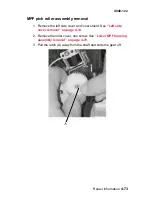
Страница 194: ...ase the spring A from the metal anchor 2 With the screwdriver remove the backup feed roller assembly Note A third assembly is below the upper MPF housing When one assembly needs replacing replace all three assemblies one at a time The assembly with the black roller should be installed in the back farthest from the door ...

Страница 195: ...ssembly removal 1 Remove the left side cover and inner shield See Left side cover removal on page 4 14 2 Remove the roller cover one screw See Lower MPF housing assembly removal on page 4 70 3 Pull the latch A away from the shaft and slide the gear off ...

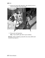
Страница 196: ...screws B holding the roller assembly and one screw C facing the front of the printer 5 Remove the roller assembly Note Push the MPF plate down to give clearance Warning When reinstalling replace the two screws B first and then the front screw C ...

Страница 197: ...removal 1 Remove the right side cover See Right side cover removal on page 4 12 2 Disconnect the HVPS cable at the top left corner of the board 3 Remove the four screws A 4 Disconnect the charge roll cable spade connector 5 Remove the HVPS card ...

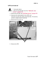
Страница 198: ...4 76 Service Manual 4048 1xx LVPS fan removal 1 Remove the right side cover See Right side cover removal on page 4 12 2 Disconnect the fan A 3 Remove the two screws B 4 Remove the LVPS fan ...

Страница 199: ...over See Right side cover removal on page 4 12 3 Remove the LVPS fan See LVPS fan removal on page 4 76 4 Disconnect all cables attached to the LVPS card The fuser connector has a latch on the back side If it cannot be reached complete steps 5 and 6 first 5 Remove the four screws A 6 Remove the LVPS ...

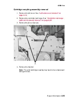
Страница 200: ...val on page 4 48 2 Remove the fuser See Fuser assembly removal on page 4 26 3 Remove the charge roll See Charge roll removal on page 4 38 4 Remove the remaining screws fastening the top cover and tilt the cover forward onto the front cover 5 Remove the screw behind the card cage which holds the outer link assembly and the inner link together 6 Remove the screw behind the card cage which fastens th...

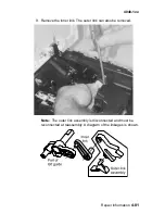
Страница 201: ...Repair information 4 79 4048 1xx 7 Use a flat blade screwdriver to wedge the charge roll arm from the left guide assembly and remove the inner link ...

Страница 202: ...4 80 Service Manual 4048 1xx 8 Remove the bellcrank while holding the link guide ...

Страница 203: ...ir information 4 81 4048 1xx 9 Remove the inner link The outer link can also be removed Note The outer link assembly is disconnected and must be reconnected at reassembly A diagram of the linkages is shown ...

Страница 204: ... Cooling fan removal 1 Remove the top cover See Top cover assembly removal on page 4 11 2 Remove the right side cover See Right side cover removal on page 4 12 3 Disconnect the fan cable 4 Remove the two screws A 5 Remove the fan ...

Страница 205: ...Locations and connections 5 1 4048 1xx 5 Locations and connections Exterior locations ...

Страница 206: ... the printed circuit card by either a white triangle a number 1 or both The pin numbers follow chronologically to the opposite end of the connector Voltages shown on the following pages are made with the printer turned on CAUTION Voltages are exposed Controller card assembly ...

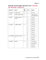
Страница 207: ...f pins Pin Signal J1 MMTR Mirror motor 5 4 Ground 5 24 V dc J2 CO Cover 3 2 5 V dc 3 Ground J3 LSU LSU printhead 10 3 Ground 6 Ground 7 5 V dc cover closed 9 Ground J4 DIMM SDRAM 100 1 Ground 12 Ground 21 3 3 V dc 26 Ground 36 Ground 42 3 3 V dc 47 Ground 50 3 3 V dc 51 Ground 56 3 3 V dc 62 Ground 71 3 3 V dc 76 Ground 81 3 3 V dc ...

Страница 208: ...24 V dc 5 24 V dc J7 USB USB connector 4 1 USB power 5 V dc USB cable attached J9 MPF MPF solenoid 2 1 24 V measured to ground 2 24 V measured to ground J10 MAIN MOTOR Main motor 7 1 Ground 6 Ground 7 24 V dc 8 5 V dc J12 MPF SN Sensor MPF toner 6 1 5 V dc 3 Ground 4 5 V dc 6 Ground Controller card assembly connectors see Controller card assembly on page 5 2 Connector Name of pins Pin Signal ...

Страница 209: ...ull sensor 6 1 5 V dc 3 Ground 4 5 V dc 6 Ground J17 LVPS LVPS DC power 6 1 24 V dc 2 24 V dc 3 Ground 4 Ground 5 5 V dc 6 Ground J18 THERM Thermistor Smart IC 5 1 2 5 V dc 2 Ground 5 Ground J19 HVPS HVPS 11 1 24 V fans 2 Ground fans 5 Ground 7 24 V dc Controller card assembly connectors see Controller card assembly on page 5 2 Connector Name of pins Pin Signal ...

Страница 210: ... duplex 9 1 5 V dc 3 Ground 4 5 V dc 6 Ground 7 5 V dc 9 Ground J21 TRAY 2nd drawer interface 8 1 5 V dc 2 5 V dc 3 5 V dc 4 5 V dc 5 Ground 6 24 V dc 7 5 V dc Controller card assembly connectors see Controller card assembly on page 5 2 Connector Name of pins Pin Signal ...

Страница 211: ...ly LVPS Connector Name Pins Pin Signal Controller card LVPS control CN1 5 1 Ground 110 220 Volts CN2 8 2 Ground 4 5 V dc 5 Ground 6 Ground 7 24 V dc 8 24 V dc Heater CN3 2 1 100 110 220 V ac 2 100 110 220 V ac On off switch CN4 S W 2 1 110 220 V ac 2 110 220 V ac ...

Страница 212: ...ame of Pins Pin Signal To controller card CN1 connects to J19 on the controller card 8 2 Ground 4 24 V dc 7 5 V dc C Charge roll Terminal DC Photoconductor Contact T Transfer roll Contact DEV Development roll Contact TAR Toner adder roll Contact Dr B Doctor blade Contact ...

Страница 213: ...pecially in the area of the on off switch and the power supply Damaged missing or altered covers especially in the area of the top cover and the power supply cover Possible safety exposure from any non Lexmark attachments Lubrication specifications Lubricate only when parts are replaced or as needed not on a scheduled basis Use of lubricants other than those specified can cause premature failure S...

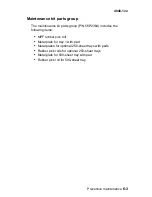
Страница 214: ... clear the 80 Scheduled Maintenance message See Reset Maint Cnt on page 3 22 Description Part number 110 V maintenance kit 56P2333 220 V maintenance kit 56P2337 100 V maintenance kit 56P2338 Maintenance kit contents Description Part number Tray 1 paper feed roll 56P2352 Transfer roll assembly 56P2329 Charge roll 56P0640 Fuser assembly See note below Rear cover assembly 56P2302 Lower MPF housing as...

Страница 215: ...it parts group P N 56P2364 includes the following items MPF rubber pick roll Metal plate for tray 1 with pad Metal plates for optional 250 sheet trays with pads Rubber pick rolls for optional 250 sheet trays Metal plate for 500 sheet tray with pad Rubber pick roll for 500 sheet tray ...

Страница 216: ...6 4 Service Manual 4048 1xx ...

Страница 217: ...ot Shown in the Asm Index column indicates that the part is procurable but is not pictured in the illustration 101 102 or 111 FRUs may be identified by model numbers The following table lists the models and their descriptions Machine type and model Description 4048 101 Duplex non network 4048 102 Duplex network 4048 111 Simplex non network ...

Страница 218: ...7 2 Service Manual 4048 1xx Assembly 1 Covers ...

Страница 219: ...ly 3 56P2306 1 Top cover assembly 4 56P2307 1 Right cover assembly 5 56P2305 1 Front cover assembly 6 56P2303 1 MPF door cover assembly 7 56P2342 1 Language overlay group 8 56P2353 1 Operator panel assembly 8 56P2356 1 Operator panel assembly Japan 9 56P2343 1 Clear bezel with logo 10 56P2354 1 Operator panel cable cover 11 56P2300 1 Left cover assembly ...

Страница 220: ...7 4 Service Manual 4048 1xx Assembly 2 Paper feed ...

Страница 221: ...ly 9 56P0634 1 Paper feed gear 10 56P2308 1 Backup feed roller assembly top front and rear 11 56P2326 1 Drive assembly Order a lubricant to use with these gears P N 99A0394 FRU Nyogel 744 See page 4 6 12 56P2334 1 Paper feed drive bushing 13 56P2325 1 Main drive motor assembly 14 56P0638 1 Cartridge coupling 15 56P2363 1 Ratchet drive Order a lubricant to use with these gears P N 99A0394 FRU Nyoge...

Страница 222: ...7 6 Service Manual 4048 1xx Assembly 3 Frame ...

Страница 223: ...P0629 1 Cartridge contact assembly includes 5 3 56P0662 1 Base feet 4 56P0661 1 Tray damper 5 56P0668 1 Parts packet screws and E rings 6 56P2310 1 Main tray assembly 250 7 56P0667 1 Door latch includes 3 8 56P0660 1 Paper guide roller 9 56P0672 1 Tray body bracket includes 4 10 56P2351 1 Entrance guide assembly with brush ...

Страница 224: ...Part numbers Units Description 4 1 56P2312 1 Upper MPF housing assembly 2 56P2311 1 Lower MPF housing assembly 3 56P0615 1 MPF paper feed cover cap 4 56P2359 1 MPF pick roll assembly 5 56P2358 1 MPF paper pick gear order lubricant to use with this gear P N 99A0394 1 3 4 5 2 ...

Страница 225: ...sembly 5 Fuser Asm index Part numbers Units Description 5 1 56P2330 1 Fuser assembly 110 V 1 56P2331 1 Fuser assembly 220 V 1 56P2332 1 Fuser assembly 100 V 2 56P2355 1 Fuser paper exit guide assembly 3 56P0676 1 Fuser exit spring ...

Страница 226: ...7 10 Service Manual 4048 1xx Assembly 6 Charging ...

Страница 227: ...omer replaceable unit is a different part number order CRU P N 56P2341 2 56P0668 1 Parts packet screws and E rings 3 56P0669 1 Pivot hinge quantity 2 4 56P2328 1 Right guide assembly 5 56P2329 1 Transfer roll assembly 6 56P2340 1 Left guide assembly 7 56P2349 1 Fuser lift inner link 8 56P2348 1 Fuser lift outer link assembly ...

Страница 228: ...7 12 Service Manual 4048 1xx Assembly 7 Electronics and cables 1 ...

Страница 229: ... fuser fan HVPS Main fan LVPS power LVPS control Paper input sensor duplex 3 56P2320 1 Power supply 110 V 3 56P2321 1 Power supply 220 V 3 56P2339 1 Power supply 100 V 4 56P2322 1 High voltage power supply 5 56P2340 1 Left guide assembly only the end of the cable shown 6 56P2369 1 Controller card assembly non network 101 111 6 56P2370 1 Controller card assembly network 102 7 56P2318 1 Printhead ca...

Страница 230: ...7 14 Service Manual 4048 1xx Assembly 8 Electronics and cables 2 ...

Страница 231: ...le only with P N 56P2311 6 and 8 56P2313 2 Paper feed solenoid 7 56P0653 1 Toner level sensor 9 56P2324 1 Drawer cable assembly 10 56P2316 1 Motor cable assembly 11 56P2336 1 Output full and fuser exit cable assembly 12 Double 3 pin connector available only with P N 56P2336 13 56P2350 1 Cartridge signature button switch attached cable shown 14 56P0682 1 Output full sensor cable 15 56P0665 1 3 pin ...

Страница 232: ...7 16 Service Manual 4048 1xx Assembly 8 cont Electronics and cables II ...

Страница 233: ...ria Belgium Bosnia Bulgaria Catalan Croatia Czech Egypt Albania Euro English and other East Finland France Germany Greece Hungary Iceland Iran Italy Jordan Lebanon Macedonia Netherlands Norway Paraguay Poland Portugal Romania Russia and CIS Slovak countries Slovenia Spain Sweden Syria Turkey Yugoslavia Serbia and Montenegro HV 19 1339530 1 Power cord Israel HV 19 1339531 1 Power cord Switzerland H...

Страница 234: ...7 18 Service Manual 4048 1xx Assembly 9 Sensors ...

Страница 235: ...its Description 9 1 56P0645 1 Photo sensor locations found A Paper path exit flag B Fuser exit sensor C Paper path below cartridge D Paper path duplex E Paper path MPF F Paper path below cartridge 2 56P0653 1 Toner level sensor 3 56P2350 1 Cartridge signature button switch ...

Страница 236: ...7 20 Service Manual 4048 1xx Assembly 10 Options 1 2 3 4 ...

Страница 237: ...h card assembly NS 56P3845 1 Lexmark Forms card assembly NS 56P3304 1 ImageQuick card assembly T430 NS 56P3305 1 PRESCRIBE card assembly NS 56P3144 1 PrintCryption card NS 56P3317 1 Bar code card NS 56P1429 1 Simplified Chinese font card assembly NS 56P1430 1 Traditional Chinese font card assembly NS 56P1438 1 Japanese font card assembly NS 56P2231 1 Korean font card assembly NS 12G9833 1 MarkNet ...

Страница 238: ...Description NS 7370971 1 Field relocation kit NS 56P2333 1 110 V maintenance kit NS 56P2337 1 220 V maintenance kit NS 56P2338 1 100 V maintenance kit NS 56P2364 1 Maintenance kit parts group see Maintenance kit parts group on page 6 3 NS 56P2341 1 Customer replaceable CRU charge roll ...

Страница 239: ...ing assembly parts 7 5 removal 4 65 charge roll removal 4 38 tests 3 17 Config Menu Demo Mode 3 24 description 3 1 Download Emuls 3 24 Energy Conserve 3 25 entering 3 21 Env Prompts 3 26 Error Log Print Log 3 26 Exit Config Menu 3 26 Factory Defaults 3 24 Maint Cnt Value 3 22 Panel Menus 3 23 Paper Prompts 3 26 PPDS Emulation 3 23 Prt Quality Pgs 3 23 Reduced Curl 3 26 Reset Maint Cnt 3 22 configu...

Страница 240: ... Par S Strobe Adj 3 16 Perm Page Count 3 16 Registration 3 4 Download Emuls 3 24 DRAM Test 3 7 duplex assembly parts catalog 7 5 tray removal 4 24 Duplex Feed 1 3 11 duplex input sensor Sensor Test 3 11 E Edge to Edge 3 16 Energy Conserve 3 25 Env Prompts 3 26 EP defaults 3 17 error codes 2 6 error log Clear Log 3 20 Display Log 3 18 Print Log 3 19 Print Log configuration menu 3 26 error messages ...

Страница 241: ...y lubrication 4 6 parts catalog 7 5 removal 4 55 main drive motor assembly parts catalog 7 5 removal 4 53 service check 2 42 maintenance handling ESD sensitive parts 4 1 lubrication 4 6 maintenance kit 6 2 maintenance kit parts group 6 3 preventive 6 1 maintenance approach 1 1 maintenance kits 6 2 media input sources 1 9 options 1 8 output sources 1 10 paper sources 1 8 memory options 1 5 messages...

Страница 242: ...nt quality 1 4 2 56 black page 2 51 blank page 2 50 2 58 does not print 2 60 faint images 2 57 heavy background 2 52 light or blurred characters 2 56 light print 2 54 Load Paper displays 2 60 media skews 2 59 multiple feeds 2 59 paper fails to feed 2 59 paper sticks 2 59 poor fusing 2 53 repeating marks 2 57 solid black areas 2 58 streaks 2 57 Toner Low does not display 2 58 Toner Low message 2 58...

Страница 243: ...able 4 20 output tray full flags 4 18 paper detect bracket 4 44 paper guide roller 4 37 printhead 4 46 ratchet drive 4 60 reference feed assembly 4 62 right guide 4 39 transfer roll assembly 4 43 tray 1 D roll shaft assembly 4 45 tray 1 feed D roll 4 44 tray damper and spring 4 35 upper MPF housing assembly 4 66 resolution 1 4 S safety information i xvii safety inspection guide 6 1 scheduled maint...

Страница 244: ...codes 2 24 supplies 1 6 symptoms POST symptoms 2 3 printer symptoms 2 4 T test pages duplex quick test 3 9 input source 3 5 input tray feed 3 12 print quality pages 3 23 Prt Quality Pgs 3 6 Quick Test 3 4 tests Device Tests 3 14 Duplex Tests 3 9 EP Setup 3 17 Hardware Tests 3 6 Input Tray Tests 3 12 Print Tests 3 5 Printer Setup 3 15 Quick Test page 3 4 Registration 3 4 tools 1 2 Top Margin 3 10 t...

Страница 245: ...17 1339534 Power cord 7 17 1339548 Power cord 7 17 43H5545 Power cord 7 17 56P0615 MPF paper feed cover cap 7 8 56P0624 Cover switch cable assembly 7 15 56P0625 Interlock cover switch 7 15 56P0629 Cartridge contact assembly 7 7 56P0634 Paper feed gear 7 5 56P0638 Cartridge coupling 7 5 56P0639 Guide bracket 7 5 56P0640 Charge roll 6 2 7 11 56P0645 Photo sensor 7 5 7 15 7 19 56P0649 Fuser exit cabl...

Страница 246: ...4 7 6 2 7 3 56P2303 MPF door cover assembly 7 3 56P2304 Stack control flags output tray full flags 7 5 56P2305 Front cover assembly 7 3 56P2306 Top cover assembly 7 3 56P2307 Right cover assembly 7 3 56P2308 Backup feed roller assembly top front and rear 7 5 56P2309 Reference feed CBM 7 5 56P2310 Main tray assembly 250 7 7 56P2311 Lower MPF housing assembly 6 2 7 8 56P2312 Upper MPF housing assemb...

Страница 247: ...uter link assembly 7 11 56P2349 Fuser lift inner link 7 11 56P2350 Cartridge signature button switch 7 15 7 19 56P2351 Entrance guide assembly with brush 7 7 56P2352 Paper feed roll 6 2 7 5 56P2353 Operator panel assembly 7 3 56P2354 Operator panel cable cover 7 3 56P2355 Fuser paper exit guide assembly 7 9 56P2356 Operator panel assembly Japan 7 3 56P2357 LVPS fan and housing assembly 7 13 56P235...

Страница 248: ...I 10 Service Manual 4048 1xx 99A0394 Lubricant Nyogel 744 4 6 6 1 6 2 7 5 7 8 99A0462 Lubricant IBM 23 4 6 99A0545 External serial adapter 7 21 ...

Страница 249: ......

Отзывы: