Repair information
4-45
4048-1xx
D–roll shaft assembly removal, tray 1
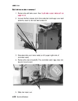
1. Remove the left side cover. See
“Left side cover removal” on
page 4-14
.
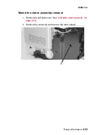
2. Remove the gear train assembly. See
“Main drive assembly
removal” on page 4-55
.
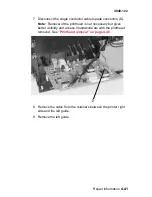
3. Remove the screw and solenoid (A).
4. With the printer on its back, remove the D–roll. See
“D–roll
feed removal, tray 1” on page 4-44
.
Note: Slowly remove the shaft (B) while facing the D–roll end
(see
page 4-44
). Capture the small washer and the bearing.
The bearing must be removed and the new one reinserted
through the opening adjacent to its operating location.
Содержание T 430
Страница 14: ...xiv Service Manual 4048 1xx Japanese Laser Notice Chinese Laser Notice ...
Страница 15: ...Laser notices xv 4048 1xx Korean Laser Notice ...
Страница 16: ...xvi Service Manual 4048 1xx ...
Страница 21: ...Safety information xxi 4048 1xx ...
Страница 34: ...1 12 Service Manual 4048 1xx ...
Страница 122: ...3 28 Service Manual 4048 1xx ...
Страница 143: ...Repair information 4 21 4048 1xx 8 Disconnect the cable from the operator panel card ...
Страница 202: ...4 80 Service Manual 4048 1xx 8 Remove the bellcrank while holding the link guide ...
Страница 205: ...Locations and connections 5 1 4048 1xx 5 Locations and connections Exterior locations ...
Страница 216: ...6 4 Service Manual 4048 1xx ...
Страница 218: ...7 2 Service Manual 4048 1xx Assembly 1 Covers ...
Страница 220: ...7 4 Service Manual 4048 1xx Assembly 2 Paper feed ...
Страница 222: ...7 6 Service Manual 4048 1xx Assembly 3 Frame ...
Страница 226: ...7 10 Service Manual 4048 1xx Assembly 6 Charging ...
Страница 228: ...7 12 Service Manual 4048 1xx Assembly 7 Electronics and cables 1 ...
Страница 230: ...7 14 Service Manual 4048 1xx Assembly 8 Electronics and cables 2 ...
Страница 232: ...7 16 Service Manual 4048 1xx Assembly 8 cont Electronics and cables II ...
Страница 234: ...7 18 Service Manual 4048 1xx Assembly 9 Sensors ...
Страница 236: ...7 20 Service Manual 4048 1xx Assembly 10 Options 1 2 3 4 ...
Страница 249: ......


