Repair information
4-63
4048-1xx
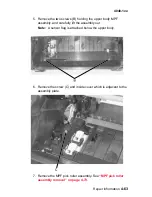
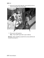
5. Remove the two screws (B) holding the upper body MPF
assembly. and carefully lift the assembly out.
Note: A sensor flag is attached below the upper body.
6. Remove the screw (C) and inside cover which is adjacent to the
assembly plate.
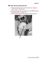
7. Remove the MPF pick roller assembly. See
“MPF pick roller
assembly removal” on page 4-73
.
Содержание T 430
Страница 14: ...xiv Service Manual 4048 1xx Japanese Laser Notice Chinese Laser Notice ...
Страница 15: ...Laser notices xv 4048 1xx Korean Laser Notice ...
Страница 16: ...xvi Service Manual 4048 1xx ...
Страница 21: ...Safety information xxi 4048 1xx ...
Страница 34: ...1 12 Service Manual 4048 1xx ...
Страница 122: ...3 28 Service Manual 4048 1xx ...
Страница 143: ...Repair information 4 21 4048 1xx 8 Disconnect the cable from the operator panel card ...
Страница 202: ...4 80 Service Manual 4048 1xx 8 Remove the bellcrank while holding the link guide ...
Страница 205: ...Locations and connections 5 1 4048 1xx 5 Locations and connections Exterior locations ...
Страница 216: ...6 4 Service Manual 4048 1xx ...
Страница 218: ...7 2 Service Manual 4048 1xx Assembly 1 Covers ...
Страница 220: ...7 4 Service Manual 4048 1xx Assembly 2 Paper feed ...
Страница 222: ...7 6 Service Manual 4048 1xx Assembly 3 Frame ...
Страница 226: ...7 10 Service Manual 4048 1xx Assembly 6 Charging ...
Страница 228: ...7 12 Service Manual 4048 1xx Assembly 7 Electronics and cables 1 ...
Страница 230: ...7 14 Service Manual 4048 1xx Assembly 8 Electronics and cables 2 ...
Страница 232: ...7 16 Service Manual 4048 1xx Assembly 8 cont Electronics and cables II ...
Страница 234: ...7 18 Service Manual 4048 1xx Assembly 9 Sensors ...
Страница 236: ...7 20 Service Manual 4048 1xx Assembly 10 Options 1 2 3 4 ...
Страница 249: ......


