4-50
Service Manual
4048-1xx
Controller card assembly removal
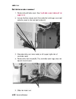
Warning: Never replace both the operator panel and controller card
at the same time. Otherwise, some critical settings will be
permanently lost.
1. Remove the left side cover. See
“Left side cover removal” on
page 4-14
.
2. Remove the screw (A) and remove the inner shield.
3. Loosen the five screws (B) in the controller card cage cover and
slide the cover to the rear and remove it.
Содержание T 430
Страница 14: ...xiv Service Manual 4048 1xx Japanese Laser Notice Chinese Laser Notice ...
Страница 15: ...Laser notices xv 4048 1xx Korean Laser Notice ...
Страница 16: ...xvi Service Manual 4048 1xx ...
Страница 21: ...Safety information xxi 4048 1xx ...
Страница 34: ...1 12 Service Manual 4048 1xx ...
Страница 122: ...3 28 Service Manual 4048 1xx ...
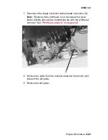
Страница 143: ...Repair information 4 21 4048 1xx 8 Disconnect the cable from the operator panel card ...
Страница 202: ...4 80 Service Manual 4048 1xx 8 Remove the bellcrank while holding the link guide ...
Страница 205: ...Locations and connections 5 1 4048 1xx 5 Locations and connections Exterior locations ...
Страница 216: ...6 4 Service Manual 4048 1xx ...
Страница 218: ...7 2 Service Manual 4048 1xx Assembly 1 Covers ...
Страница 220: ...7 4 Service Manual 4048 1xx Assembly 2 Paper feed ...
Страница 222: ...7 6 Service Manual 4048 1xx Assembly 3 Frame ...
Страница 226: ...7 10 Service Manual 4048 1xx Assembly 6 Charging ...
Страница 228: ...7 12 Service Manual 4048 1xx Assembly 7 Electronics and cables 1 ...
Страница 230: ...7 14 Service Manual 4048 1xx Assembly 8 Electronics and cables 2 ...
Страница 232: ...7 16 Service Manual 4048 1xx Assembly 8 cont Electronics and cables II ...
Страница 234: ...7 18 Service Manual 4048 1xx Assembly 9 Sensors ...
Страница 236: ...7 20 Service Manual 4048 1xx Assembly 10 Options 1 2 3 4 ...
Страница 249: ......

