background image

8

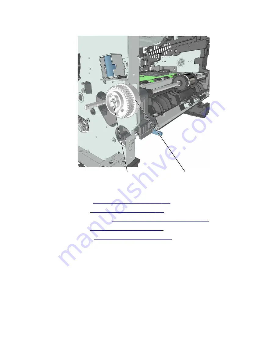
Remove the E-clip (E), and then remove the MPF sector gear (F).

E

F

Reverse solenoid removal

1

Remove the right cover. See 

“Right cover removal” on page 222

.

2

Remove the left cover. See 

“Left cover removal” on page 207

.

3

Remove the rear door and cover. See 

“Rear door and cover removal” on page 270

.

4

Remove the top cover. See 

“Top cover removal” on page 277

.

5

Remove the cooling fan. See 

“Cooling fan removal” on page 222

.

6

Disconnect cable JDRSOL1 from the controller board.

4514-330

Parts removal

216

Содержание MS312

Страница 1: ...MS312 and MS317 4514 330 Service Manual Start diagnostics Maintenance Safety and notices Trademarks Index July 12 2018 www lexmark com P N 12G3396 ...

Страница 2: ...e to a product program or service is not intended to state or imply that only that product program or service may be used Any functionally equivalent product program or service that does not infringe any existing intellectual property right may be used instead Evaluation and verification of operation in conjunction with other products programs or services except those expressly designated by the ma...

Страница 3: ... required for service 35 Diagnostics and troubleshooting 37 Troubleshooting overview 37 Performing the initial troubleshooting check 37 Power on Reset POR sequence 37 Fixing print quality issues 38 Initial print quality check 38 Gray background or toner fog check 39 Blank pages check 41 Solid black pages check 47 Print is too dark check 50 Print is too light check 52 Paper curl check 54 Folded or ...

Страница 4: ...x 85 Jam MP feeder 250 xx 86 200 paper jams 87 201 paper jams 92 202 paper jams 93 23y paper jams 95 241 paper jams 96 242 paper jams 99 25y paper jams 101 Understanding the printer messages 103 Bin full Remove paper 103 Cannot collate large document 37 103 Cannot defrag flash memory 37 103 Cartridge imaging unit mismatch 41 xy 103 Cartridge low 88 xy 103 Cartridge nearly low 88 xy 104 Cartridge ve...

Страница 5: ...nt quota exceeded Print job incomplete 110 Printer restart Check last job 110 Rear USB port disabled 56 111 Reinstall missing or unresponsive cartridge 31 xy 111 Reinstall missing or unresponsive imaging unit 31 xy 111 Replace cartridge 0 estimated pages remain 88 xy 111 Replace cartridge printer region mismatch 42 xy 111 Replace imaging unit 0 estimated pages remain 84 xy 112 Replace unsupported ...

Страница 6: ...e check 150 Option tray separator pass through motor service check 150 Option tray ACM motor service check 151 Option tray controller card service check 151 Other symptoms 152 Base printer symptoms 152 Cooling fan service check 152 Dead machine service check 153 Controller board service check 153 Control panel button service check 154 Control panel service check 155 Toner starvation service check ...

Страница 7: ...efaults 176 Reports 176 Tray Linking 177 Panel Menus 177 PPDS Emulation 177 Print Quality Pages 177 A5 Loading 177 Reduced Curl 177 Safe Mode 178 Demo Mode 178 Energy Conserve 178 Wipe All Settings 178 Font Density 178 Font Sharpening 179 USB Speed 179 USB PnP 179 Exit Config Menu 179 Entering Invalid engine mode 179 Entering Recovery mode 179 Accessing the Network SE menu 180 Service engineer menu...

Страница 8: ...ide removals 207 Left cover removal 207 Main drive gearbox removal 208 MPF solenoid removal 210 MPF gearbox removal 213 Reverse solenoid removal 216 ACM clutch removal 217 Cartridge gearbox removal 219 Duplex gear assembly removal 220 Right side removals 222 Right cover removal 222 Cooling fan duct removal 222 Cooling fan removal 222 Controller board removal 223 Toner cartridge smart chip contact ...

Страница 9: ...oor and cover removal 270 Narrow media bin full sensor removal 271 Redrive assembly removal 273 Redrive shaft removal 274 Fuser removal 276 Top side removals 277 Top cover removal 277 Laser scanning unit LSU removal 278 250 550 sheet option tray removals 280 Pick roller removal 280 Separator roll assembly removal 281 ACM assembly removal 283 Component locations 287 Exterior locations 287 Front vie...

Страница 10: ...the security reset jumper 311 Options and features 313 Available internal options 313 Media handling options 313 Theory of operation 315 POR sequence 315 Printer control 315 Paper path information 315 Input tray 315 Multipurpose feeder MPF 315 Simplex printing 316 Duplex printing 317 Media handling components 318 Main drive gearbox 318 Autocompensator mechanism ACM 318 Key components 319 Sensors 3...

Страница 11: ...Part number index 335 Part name index 339 4514 330 Table of contents 11 ...

Страница 12: ...4514 330 Table of contents 12 ...

Страница 13: ...lisateur ou de la maintenance Notificació del làser La impressora està certificada als EUA per complir els requeriments de DHHS 21 CFR capítol I subcapítol J per a productes de làser Classe I 1 i a la resta del món s ha certificat com productes de làser Classe I segons els requeriments de la norma IEC 60825 1 2014 Els productes de làser Classe I no es consideren perillosos La impressora conté un làse...

Страница 14: ...erenigde Staten gecertificeerd als een product dat voldoet aan de vereisten van DHHS 21 CFR hoofdstuk 1 paragraaf J voor laserproducten van klasse I 1 Elders is de printer gecertificeerd als een laserproduct van klasse I dat voldoet aan de vereisten van IEC 60825 1 2014 Laserproducten van klasse I worden geacht geen gevaar op te leveren De printer bevat een interne laser van klasse IIIb 3b een galli...

Страница 15: ... 2014 Laserprodukter av klasse I anses ikke som helseskadelige Skriveren inneholder en intern laser av klasse IIIb 3b som nominelt er en 12 milliwatt galliumarsenid laser som opererer i bølgelengder på 655 675 nanometer Lasersystemet og skriveren er utformet slik at mennesker ikke utsettes for laserstråling utover nivået i klasse I under normal drift vedlikehold eller foreskrevet service Meddeland...

Страница 16: ...s Note A note identifies information that could help you Warning A warning identifies something that could damage the product hardware or software CAUTION A caution indicates a potentially hazardous situation that could injure you Different types of caution statements include CAUTION POTENTIAL INJURY Indicates a risk of injury CAUTION SHOCK HAZARD Indicates a risk of electrical shock CAUTION HOT SUR...

Страница 17: ...mencer ou agissez avec prudence si le produit doit être alimenté pour effectuer l opération ATTENTION RISQUE DE BLESSURE La batterie lithium de ce produit n est pas destinée à être remplacée Si vous ne respectez pas les instructions de remplacement de la batterie vous risquez de provoquer une explosion Ne rechargez pas ne désassemblez pas et ne brûlez pas la batterie au lithium Mettez les batterie...

Страница 18: ...ças de substituição As informações sobre manutenção deste produto foram preparadas para utilização por um técnico profissional experiente e não se destinam ao uso por outros Pode haver maior risco de choque elétrico e danos pessoais durante a desmontagem e manutenção deste produto Os técnicos profissionais experientes devem entender esses riscos e tomar as precauções necessárias ATENÇÃO RISCO DE CHO...

Страница 19: ...contact voordat u begint of let extra goed op als het product stroom nodig heeft om een taak te kunnen uitvoeren LET OP RISICO OP LETSEL De lithiumbatterij in dit product moet niet worden vervangen Wanneer de lithiumbatterij niet juist wordt vervangen bestaat er explosiegevaar Probeer nooit lithiumbatterijen op te laden open te maken of te verbranden Gooi gebruikte lithiumbatterijen weg volgens de...

Страница 20: ...Valmistaja ei vastaa turvallisuudessa jos laitteessa on käytetty luvattomia vaihto osia Tämän tuotteen huoltoa koskevat tiedot on tarkoitettu vain ammattitaitoisen huoltohenkilön käyttöön Tämän tuotteen purkamiseen ja huoltoon voi liittyä kasvanut sähköiskun tai henkilövahingon vaara Ammattitaitoisen huoltohenkilön on ymmärrettävä tämä vaara ja toimittava sen edellyttämällä tavalla HUOMIO SÄHKÖISK...

Страница 21: ...dukten måste vara strömförsörjd för att uppgiften ska kunna utföras VAR FÖRSIKTIG RISK FÖR SKADA Litiumbatteriet i produkten är inte utbytbart Om ett litiumbatteri byts ut på fel sätt finns det risk att det exploderar Du får inte ladda om ta isär eller elda upp ett litiumbatteri Gör dig av med använda litiumbatterier enligt tillverkarens instruktioner och lokala föreskrifter 安全情報 本製品の安全性は 本来の設計 特定コ...

Страница 22: ...o avoid the risk of fire or electrical shock connect the power cord to an appropriately rated and properly grounded electrical outlet that is near the product and easily accessible CAUTION POTENTIAL INJURY To avoid the risk of fire or electrical shock use only the power cord provided with this product or the manufacturer s authorized replacement CAUTION POTENTIAL INJURY Do not use this product with ...

Страница 23: ...shooting chapter December 19 2017 Updated the graphic for PN 40X8302 to include the MPF links in the assembly Added PN 41X2300 for the access cover link under the Covers assembly in the Parts Catalog chapter Deleted the topic Invalidating the effects of a jumper reset in the Printer specifications section August 30 2017 Updated Blank pages check on page 41 Updated Solid black pages check on page 47...

Страница 24: ...e Diagnostic information chapter Updated the topic Unresponsive imaging unit service check in the Diagnostic information chapter June 2 2016 Updated the graphic of the Electronics 2 topic in the Parts catalog chapter Corrected the Electronics 1 topic in the Parts catalog chapter March 23 2016 Revised the topic Covers in the Parts catalog chapter Revised the following topics in the Diagnostic infor...

Страница 25: ...cs 1 on page 295 to add PN 41X0913 for the video cable that is applicable only for models with galvo LSU June 18 2015 Updated Frame on page 300 to change the part numbers for the pick tires from 41X0547 to 41X0918 and ACM assembly 40X8260 to 41X0919 May 13 2015 Updated 200 paper jam messages on page 87 to add error codes specific to polygon laser scanning unit LSU Updated 111 error messages on page...

Страница 26: ...ber 4 2014 Updated the LSU removal procedure October 17 2014 Updated the ACM clutch removal procedure Frame parts catalog assembly table Removed the insulated displacement connectors IDC from 40X8265 October 9 2014 Updated the illustration of Electronics 2 parts catalog assembly to show the correct toner cartridge smart chip contact September 8 2014 Changed part number 40X8296 to 41X0547 August 15...

Страница 27: ...est print quality try a sample of the paper or specialty media before buying large quantities Paper characteristics The following paper characteristics affect print quality and reliability Consider these characteristics when evaluating new paper stock Weight The printer trays can automatically feed paper weights up to 90 g m2 24 lb bond grain long paper The multipurpose feeder can automatically fe...

Страница 28: ...r is recommended Fiber content Most high quality xerographic paper is made from 100 chemically treated pulped wood This content provides the paper with a high degree of stability resulting in fewer paper feeding problems and better print quality Paper containing fibers such as cotton can negatively affect paper handling Unacceptable paper The following paper types are not recommended for use with t...

Страница 29: ...p to 230 C 446 F without melting or releasing hazardous emissions Using recycled paper and other office papers As an environmentally conscientious company Lexmark supports the use of recycled paper produced specifically for use in laser electrophotographic printers While no blanket statement can be made that all recycled paper will feed well Lexmark consistently tests papers that represent recycled...

Страница 30: ...e following paper choice guidelines will help alleviate the environmental impact of printing 1 Minimize paper consumption 2 Be selective about the origin of wood fiber Buy from suppliers who carry certifications such as the Forestry Stewardship Council FSC or the Program for the Endorsement of Forest Certification PEFC These certifications guarantee that the paper manufacturer uses wood pulp from fore...

Страница 31: ...nd creasing may significantly affect the print quality and cause jams or other paper handling problems Check with the manufacturer or vendor to ensure that the card stock can withstand temperatures up to 240 C 464 F without releasing hazardous emissions Do not use preprinted card stock manufactured with chemicals that may contaminate the printer Preprinting introduces semi liquid and volatile compo...

Страница 32: ...the cartridge with adhesive and could void the printer and toner cartridge warranties Do not use labels with exposed adhesive Do not print within 1 mm 0 04 inch of the edge of the label of the perforations or between die cuts of the label Make sure the adhesive backing does not reach to the edge of the sheet Zone coating of the adhesive should be at least 1 mm 0 04 inch away from edges Adhesive ma...

Страница 33: ...x 13 in Statement 140 x 216 mm 5 5 x 8 5 in X Universal2 76 2 x 127 mm 3 x 5 in up to 216 x 356 mm 8 5 x 14 in 7 3 4 Envelope Monarch 98 x 191 mm 3 9 x 7 5 in X X X 9 Envelope 98 x 225 mm 3 9 x 8 9 in X X X 1 This size setting formats the page for 216 x 356 mm 8 5 x 14 in unless the size is specified by the software application 2 Universal is supported only in the standard tray if the paper size is...

Страница 34: ...he optional 250 or 550 sheet tray if the paper size is at least 148 x 210 mm 5 8 x 8 3 in Universal is only supported in duplex mode if the width is at least 210 mm 8 3 in and length is at least 279 mm 11 in The smallest supported Universal size is only supported in the multipurpose feeder Supported paper types and weights The standard tray supports 60 90 g m2 16 24 lb paper weights The optional t...

Страница 35: ...wo forms of non volatile memory EEPROM and NAND flash memory Both types are used to store the operating system printer settings network information scanner and bookmark settings and embedded solutions Hard disk memory The printer hard disk is designed for printer specific functionality and cannot be used for the long term storage of data that is not print related The hard disk can retain buffered us...

Страница 36: ... screwdriver magnetic 2 Phillips screwdriver magnetic short blade Needle nose pliers Diagonal side cutters Spring hook Feeler gauges Analog or digital multimeter Flashlight optional 4514 330 General information 36 ...

Страница 37: ... connections Make sure the printer is properly grounded Check the power cord ground terminal Make sure the power supply line voltage is within 10 of the rated line voltage Make sure the machine is securely installed on a level surface in a well ventilated area Make sure the room temperature is between 16 and 32 C 60 and 90 F and that the relative humidity is between 8 and 80 Avoid sites generating...

Страница 38: ...upplies Third party supplies may cause print quality problems The printer must be in a location that follows the recommended operating environment specifications See Operating environment on page 311 Check the life status of all supplies Any supply that is low should be replaced Load 20 lb plain letter or A4 paper Make sure the paper guides are properly set and locked From the control panel set the...

Страница 39: ... Quality menu Note 8 is the factory default setting 2 Set the paper type texture and weight in the Paper menu to match the paper loaded Does the problem remain Go to step 2 The problem is solved Step 2 Check if the printer is using a genuine and supported Lexmark toner cartridge Note If the printer is using a third party cartridge then refer the users to their cartridge supplier Is the printer usi...

Страница 40: ...rge roller contact damaged and contaminated Go to step 5 Go to step 6 Step 5 Repair or replace the charge roller contact on the imaging unit Does the problem remain Go to step 6 The problem is solved Step 6 Replace the imaging unit Does the problem remain Go to step 7 The problem is solved Step 7 Make sure that connection JPS1 on the controller board and the connections on the power supply are pro...

Страница 41: ...rform a print test Does the problem remain Go to step 10 The problem is solved Step 10 Check if the photoconductor charge contact is bent damaged or not in proper contact with the imaging unit Is the contact free from damage and in proper contact with the imaging unit Go to step 11 Contact the next level of support Step 11 Replace the power supply See Power supply removal on page 252 Does the prob...

Страница 42: ...l a genuine and supported toner cartridge Does the problem remain Go to step 3 The problem is solved Step 3 a Check and remove any packing material left on the imaging unit b Firmly shake the imaging unit to redistribute the toner and then reinstall it Does the problem remain Go to step 4 The problem is solved Step 4 Check the imaging unit for damage and proper installation and replace if necessar...

Страница 43: ...the door observe the coupler to see if it moves inward Note With the imaging unit removed the coupler should retract with the door open and move inward when the front door is closed Is the coupler stuck and not moving inward while closing the front door Go to step 6 Go to step 7 4514 330 Diagnostics and troubleshooting 43 ...

Страница 44: ...contact with the imaging unit Are the contacts free from damage not bent and in proper contact with the imaging unit Go to step 8 Contact the next level of support Step 8 Check all connections in the power supply If necessary replace the power supply Does the problem remain Go to step 9 The problem is solved Step 9 Reseat cable JPS1 on the controller board Does the problem remain Go to step 10 The...

Страница 45: ... contamination and damage Go to step 13 Go to step 12 Step 12 Replace the transfer roller See Transfer roll removal on page 231 Does the problem remain Go to step 13 The problem is solved Step 13 Check the transfer roller left contact spring on the transfer roller left arm for damage Is the contact spring free of damage Go to step 15 Go to step 14 Step 14 Replace the transfer roller left arm with ...

Страница 46: ...Depending on the printer model reseat the following cables on the controller board JVIDEO and JGLV1 MS31x MS41x MS51x and MS61x J6 and JLSU1 MS610de and MX61xde JMM1 and JLSU1 MX31x MX41x MX51x and MX61x Does the problem remain Go to step 17 The problem is solved Step 17 Replace the laser printhead See Laser scanning unit LSU removal on page 278 Does the problem remain Contact the next level of su...

Страница 47: ...e printer is using a third party cartridge then refer the users to their cartridge supplier Is the printer using a genuine and supported toner cartridge Go to step 3 Go to step 2 Step 2 Install a genuine and supported toner cartridge Does the problem remain Go to step 3 The problem is solved 4514 330 Diagnostics and troubleshooting 47 ...

Страница 48: ... roller contact B on the right side of the imaging unit for damage and contamination Is the charge roller contact damaged and contaminated Go to step 4 Go to step 5 Step 4 Repair or replace the charge roller contact on the imaging unit Does the problem remain Go to step 5 The problem is solved Step 5 Replace the imaging unit Does the problem remain Go to step 6 The problem is solved 4514 330 Diagn...

Страница 49: ...k the high voltage metal contacts on the imaging unit for damage If necessary replace the imaging unit Does the problem remain Go to step 9 The problem is solved Step 9 Check cable JPS1 from the controller board to the power supply for proper connection Is the cable properly connected Go to step 11 Go to step 10 Step 10 Reseat the cable Does the problem remain Go to step 11 The problem is solved S...

Страница 50: ...rkness in the Quality menu Note 8 is the factory default setting Does the problem remain Go to step 4 The problem is solved Step 4 From the control panel set the paper type texture and weight in the Paper menu to match the paper loaded Does the problem remain Go to step 5 The problem is solved Step 5 Depending on the operating system specify the paper type texture and weight from Printing Preferen...

Страница 51: ...contact with the imaging unit Are the contacts free from damage not bent and in proper contact with the imaging unit Go to step 10 Contact the next level of support Step 10 Check all connections on the power supply for proper connection Is the power supply properly connected Contact the next level of support Go to step 11 Step 11 Replace the connections Does the problem remain Go to step 12 The pr...

Страница 52: ...factory default setting 2 Set the paper type texture and weight in the Paper menu to match the paper loaded Does the problem remain Go to step 4 The problem is solved Step 4 a Remove the toner cartridge and imaging unit b Push either side of the transfer roller located below the imaging unit to check if it depresses and bounces back into place c If the transfer roller does not depress and bounce b...

Страница 53: ...e the transfer roller See Transfer roll removal on page 231 Does the problem remain Go to step 9 The problem is solved Step 9 Clean the printhead lens See Cleaning the printhead lenses on page 290 Note This is applicable only to models installed with a galvo LSU To determine whether the LSU is galvo check the serial number of the printer The sixth digit character assigned should be in the 0 9 or B...

Страница 54: ...onnected Go to step 15 Go to step 14 Step 14 Replace the connections Does the problem remain Go to step 15 The problem is solved Step 15 Replace the cartridge gearbox See Cartridge gearbox removal on page 219 Does the problem remain Go to step 16 The problem is solved Step 16 Replace the controller board See Controller board removal on page 223 Does the problem remain Contact the next level of sup...

Страница 55: ...ype and weight in the Paper menu to match the paper loaded Does the problem remain Go to step 5 The problem is solved Step 5 Depending on the operating system specify the paper size from Printing Preferences or Print dialog Does the problem remain Go to step 6 The problem is solved Step 6 Remove paper from the tray and then turn it over Does the problem remain Go to step 7 The problem is solved St...

Страница 56: ...a fresh package Note The amount of moisture in paper affects both print quality and printer ability to feed paper correctly b Make sure that the printer supports the paper loaded For a complete list of supported paper see the printer User s Guide Does the problem remain Go to step 3 The problem is solved Step 3 Make sure that the fuser entry guide is free of waste toner and dust Warning Potential ...

Страница 57: ...tep 2 Replace the imaging unit Does the problem remain Go to step 3 The problem is solved Step 3 Check if the distance between repeating defects is equal to 3 15 inches 85 mm Does the distance between repeating defects equal to 3 15 inches 85 mm Go to step 4 Contact the next level of support Step 4 Replace the fuser See Fuser removal on page 276 Does the problem remain Go to step 5 The problem is ...

Страница 58: ...nter supports the paper loaded Note For a complete list of supported paper see the printer User s Guide Is the paper supported Go to step 5 Go to step 4 Step 4 Remove the paper and then load a supported one Does the problem remain Go to step 5 The problem is solved Step 5 Check the tray pick roller for excess wear and contamination Is the pick roller free from excess wear and contamination Go to s...

Страница 59: ... the paper loaded Does the problem remain Go to step 11 The problem is solved Step 11 Check if the printer supports the paper loaded Note For a complete list of supported paper see the printer User s Guide Is the paper supported Go to step 13 Go to step 12 Step 12 Remove the paper and then load a supported one Does the problem remain Go to step 13 The problem is solved Step 13 Check the MPF pick r...

Страница 60: ...plier Is the printer using a genuine and supported toner cartridge Go to step 3 Go to step 2 Step 2 Install a genuine and supported toner cartridge Does the problem remain Go to step 3 The problem is solved Step 3 Remove and then reinstall the imaging unit Does the problem remain Go to step 4 The problem is solved Step 4 Replace the imaging unit Does the problem remain Go to step 5 The problem is ...

Страница 61: ...ter is using a third party cartridge then refer the users to their cartridge supplier Is the printer using a genuine and supported toner cartridge Go to step 3 Go to step 2 Step 2 Install a genuine and supported toner cartridge Does the problem remain Go to step 3 The problem is solved Step 3 Turn off the printer wait for 10 seconds and then turn on the printer Does the problem remain Go to step 4...

Страница 62: ...em remain Contact the next level of support The problem is solved Vertical light bands check Actions Yes No Step 1 Check if the printer is using a genuine and supported Lexmark toner cartridge Note If the printer is using a third party cartridge refer the users to their cartridge supplier Is the printer using a genuine and supported toner cartridge Go to step 3 Go to step 2 Step 2 Install a genuin...

Страница 63: ...on page 278 Does the problem remain Go to step 5 The problem is solved Step 5 Replace the imaging unit Does the problem remain Contact the next level of support The problem is solved Vertical dark bands check Actions Yes No Step 1 Check if the printer is using a genuine and supported Lexmark toner cartridge Note If the printer is using a third party cartridge then refer the users to their cartridg...

Страница 64: ...d add a cover to the fan inlet vent to block the light from entering the printer or contact the next level of support Does the problem remain Go to step 5 The problem is solved Step 5 If a separator plastic A is stuck inside the imaging unit or if there are other obstructions between the charge roller and photoconductor drum then remove them Does the problem remain Contact the next level of suppor...

Страница 65: ...3 The problem is solved Step 3 a Remove any packing material left on the imaging unit including the red separator plastic A Note You may need a pair of pliers to remove a piece of broken plastic inside the imaging unit b Check the charge roller contact B on the right side of the imaging unit for damage and proper installation Is the charge roller contact damaged and contaminated Go to step 4 Go to...

Страница 66: ...ging unit contacts Does the problem remain Go to step 8 The problem is solved Step 8 Check connection JPS1 on the controller board and the connections on the power supply Are the connections properly connected Go to step 10 Go to step 9 Step 9 Reconnect the cables Does the problem remain Go to step 10 The problem is solved Step 10 Replace the power supply See Power supply removal on page 252 Does ...

Страница 67: ...match the paper loaded Note Make sure that the printer supports the paper loaded For a complete list of supported paper see the printer User s Guide Does the problem remain Go to step 4 The problem is solved Step 4 a Update the firmware to the latest version available b Enter the Diagnostics menu and then change the EngSetting 14 value to 48 Note You can also change the setting through a bundle file...

Страница 68: ...page 290 Note This is applicable only to models installed with a galvo LSU To determine whether the LSU is galvo check the serial number of the printer The sixth digit character assigned should be in the 0 9 or B N range Example 4514 20HH 007CR Does the problem remain Go to step 8 The problem is solved Step 8 Check if the imaging unit contacts B are contaminated or bent out of proper position Are ...

Страница 69: ...tep 11 Step 11 Replace the connections Does the problem remain Go to step 12 The problem is solved Step 12 Replace the power supply See Power supply removal on page 252 Does the problem remain Go to step 13 The problem is solved Step 13 Replace the printhead See Laser scanning unit LSU removal on page 278 Does the problem remain Contact the next level of support The problem is solved Fine lines ar...

Страница 70: ... panel adjust the Toner Darkness setting to 7 a From the Settings menu navigate to Print Settings Quality menu Pixel Boost Fonts Submit b From the Quality menu select Toner Darkness and then adjust the setting to 7 c Submit the changes Note Adjusting the Toner Darkness setting to 7 results in a slightly lighter print You may leave the Toner Darkness value at 8 in order to maintain the darkness tha...

Страница 71: ...maging unit Does the problem remain Go to step 4 The problem is solved Step 4 Check if a separator plastic A or a piece of it is stuck inside the imaging unit or if there are any other obstructions between the charge roller and photoconductor drum Is the imaging unit free from any separator plastic fragments or other obstructions Go to step 6 Go to step 5 Step 5 Using a pair of pliers remove the s...

Страница 72: ... contact block damaged or improperly installed Go to step 8 Contact the next level of support Step 8 Reinstall or replace the imaging unit contact block Does the problem remain Contact the next level of support The problem is solved Compressed images appear on prints check 4514 330 Diagnostics and troubleshooting 72 ...

Страница 73: ... coupler move freely or appear damaged Go to step 2 Go to step 3 Step 2 Replace the imaging unit Does the problem remain Go to step 3 The problem is solved Step 3 Replace the main drive gearbox See Main drive gearbox removal on page 208 Does the problem remain Contact the next level of support The problem is solved Incorrect margins on prints check 4514 330 Diagnostics and troubleshooting 73 ...

Страница 74: ...ize specified in the tray settings Does the problem remain Go to step 3 The problem is solved Step 3 Depending on your operating system specify the paper size from Printing Preferences or from the Print dialog Does the problem remain Go to step 4 or contact the next level of support The problem is solved Step 4 a Enter the Diagnostics menu and then select Registration b Adjust the margins as necess...

Страница 75: ... weight in the Paper menu to match the paper loaded Does the problem remain Go to step 4 The problem is solved Step 4 Remove and then reinstall the fuser Does the problem remain Go to step 5 The problem is solved Step 5 Replace the fuser See Fuser removal on page 276 Does the problem remain Go to step 6 The problem is solved Step 6 Reseat the connections on the power supply Does the problem remain...

Страница 76: ...eakage Go to step 4 Go to step 5 Step 4 Replace the imaging unit Does the problem remain Go to step 5 The problem is solved Step 5 Check if toner specks appear only on the edges or back side of the pages Do toner specks appear only on the edges or back side of the pages Go to step 6 Go to step 7 Step 6 Replace the transfer roller See Transfer roll removal on page 231 Does the problem remain Go to ...

Страница 77: ...aper fill indicator Do not slide paper into the tray Load paper as shown in the illustration Make sure that the paper guides are properly positioned Push the tray firmly into the printer after loading paper Use recommended paper Use only recommended paper or specialty media Do not load wrinkled creased damp bent or curled paper Flex fan and straighten paper before loading it Do not use paper that ha...

Страница 78: ...am Recovery is set to On or Auto the printer reprints jammed pages However the Auto setting does not guarantee that the page will print 1 5 6 2 3 4 Area Printer control panel message What to do 1 Standard bin Jam standard bin 20y xx Remove the jammed paper 2 Rear door Jam rear door 20y xx Open the rear door and then remove the jammed paper 3 Tray 1 Jam pull tray 1 Push down blue flap 23y xx Pull tr...

Страница 79: ...it 1 Press the button on the right side of the printer and then open the front door 2 1 2 Pull the toner cartridge out using the handle 3 Lift the green handle and then pull the imaging unit out of the printer Warning Potential Damage Do not touch the photoconductor drum Doing so may affect the print quality of future print jobs 4514 330 Diagnostics and troubleshooting 79 ...

Страница 80: ...t to direct light for more than 10 minutes Extended exposure to light can cause print quality problems 5 Lift the green flap in front of the printer 6 Firmly grasp the jammed paper on each side and then gently pull it out Note Make sure all paper fragments are removed 4514 330 Diagnostics and troubleshooting 80 ...

Страница 81: ...arrows on the side rails inside the printer and then insert the cartridge into the printer 9 Close the front door 10 From the printer control panel press to clear the message and continue printing Jam standard bin 20y xx 1 Firmly grasp the jammed paper on each side and then gently pull it out Note Make sure all paper fragments are removed 2 From the printer control panel press to clear the message...

Страница 82: ...e rear door CAUTION HOT SURFACE The inside of the printer might be hot To reduce the risk of injury from a hot component allow the surface to cool before touching it 3 Firmly grasp the jammed paper on each side and then gently pull it out Note Make sure all paper fragments are removed 4514 330 Diagnostics and troubleshooting 82 ...

Страница 83: ...r and front doors 5 From the printer control panel press to clear the message and continue printing Jam pull tray 1 Push down blue flap 23y xx 1 Pull out the tray completely 4514 330 Diagnostics and troubleshooting 83 ...

Страница 84: ...per Make sure all paper fragments are removed 3 Firmly grasp the jammed paper on each side and then gently pull it out Note Make sure all paper fragments are removed 4 Insert the tray 5 From the printer control panel press to clear the message and continue printing x page jam open tray 1 241 xx 1 Pull the tray completely out of the printer 4514 330 Diagnostics and troubleshooting 84 ...

Страница 85: ...ull it out Note Make sure all paper fragments are removed 3 Insert the tray 4 From the printer control panel select Next Clear the jam press OK x page jam open tray 2 242 xx 1 Pull the tray completely out of the printer Note The message on the printer display indicates the tray where the jammed paper is located 4514 330 Diagnostics and troubleshooting 85 ...

Страница 86: ...are removed 3 Insert the tray 4 From the printer control panel select Next Clear the jam press OK Jam MP feeder 250 xx 1 From the multipurpose feeder firmly grasp the jammed paper on each side and then gently pull it out Note Make sure all paper fragments are removed 4514 330 Diagnostics and troubleshooting 86 ...

Страница 87: ...P Z range then the printer is installed with a polygon LSU example 4514 2ZHH 007CR Error code Description Action 200 01 Input sensor covered during warm up sequence Go to Sensor input static jam service check on page 89 200 02 Input sensor covered too quickly Go to Sensor input early late arriving service check on page 90 200 03 Page did not reach input sensor or was late reaching input sensor but...

Страница 88: ...ut Source Ready flag to indicate it has initiated picking Go to Sensor input early late arriving service check on page 90 200 23 Laser servo never started due to potential conflict with the transfer servo Go to Sensor input image jam service check on page 91 200 24 Measured gap at input sensor too small to meet video delivery requirements Not enough time since prior image finished to start new image ...

Страница 89: ...put early late arriving service check on page 90 Sensor input static jam service check Action Yes No Step 1 Check the input sensor area for jammed media fragments Is the paper path free of partially fed or jammed media Go to step 2 Clear the paper path of any media fragments Step 2 Check the jam access cover if it is blocking the input sensor Is it blocking the input sensor Replace the jam access ...

Страница 90: ...sure the MPF gearbox spring is properly installed and free of damage Check the MPF gearbox for wear or damage Are they free of wear or damage Go to step 5 Replace the MPF gearbox See MPF gearbox removal on page 213 Step 5 Check the input sensor area for jammed media fragments Is the paper path free of partially fed or jammed media Go to step 6 Clear the paper path of any media fragments Step 6 Che...

Страница 91: ...gnostics menu and perform a feed test Diagnostics Menu Input Tray Tests Feed Tests Tray 1 Does it pass the test Go to step 5 Replace the LSU See Laser scanning unit LSU removal on page 278 Step 5 POR into the Diagnostics menu and perform a sensor test Diagnostics Menu Base Sensor Test Input Does the sensor state on the control panel display change when it is toggled Go to step 6 Replace the input ...

Страница 92: ... rotates when doing the feed test Does it rotate when doing the feed test Go to step 4 Replace the main drive gearbox See Main drive gearbox removal on page 208 Step 4 Check the fuser gear for damage or toner contamination Is it free of damage and contamination Replace the controller board See Controller board removal on page 223 Replace the fuser See Fuser removal on page 276 201 paper jams 201 p...

Страница 93: ...ion Action 202 01 Exit sensor is covered during warm up Go to Sensor fuser exit jam service check on page 94 202 03 Media did not reach the fuser exit sensor Go to Sensor fuser exit jam service check on page 94 202 05 Exit sensor covered too long or exit sensor did not clear ahead of a sheet Go to Sensor fuser exit jam service check on page 94 202 13 Restart attempted after an internal jam without...

Страница 94: ... Sensor fuser exit jam service check on page 94 202 45 During warm up flush sheet detected too long over exit sensor Go to Sensor fuser exit jam service check on page 94 Sensor fuser exit jam service check Action Yes No Step 1 Check the input sensor area for jammed media fragments Is the paper path free of partially fed or jammed media Go to step 2 Clear the paper path of any media fragments Step 2...

Страница 95: ...versing into duplexer Go to Duplex service check on page 95 230 28 Bouncy duplex sensor never made Go to Duplex service check on page 95 232 03 Input sensor never detected sheet from internal duplex path Go to Duplex service check on page 95 232 10 Feed error picking from the duplexer Go to Duplex service check on page 95 Duplex service check Action Yes No Step 1 a Remove the rear cover See Rear d...

Страница 96: ...tep 6 Does the error remain Contact the next level of support The problem is solved 241 paper jams 241 paper jam messages Error code Description Action 241 01 Paper over tray 1 pass through sensor on warmup Go to Tray 1 jam service check on page 98 241 02 Sensor input early arriving jam Go to Tray 1 jam service check on page 98 241 03 Tray 1 pass through sensor never became covered when feeding a ...

Страница 97: ...ervice check on page 98 241 42 Media feeder motor pick motor under speed in tray 1 Go to Tray 1 jam service check on page 98 241 43 Media feeder motor stalled on the last pick attempt in tray 1 Go to Tray 1 jam service check on page 98 241 44 Motor 2 Separator Passthrough motor stalled Go to Tray 1 jam service check on page 98 241 45 Motor 2 Separator Passthrough motor PWM overflow error underspeed...

Страница 98: ...tep 7 Go to step 5 Step 5 Observe the location of the jammed paper Are the first page fed to the output bin the second page jammed in the rear door and the third page jammed in the input tray Go to step 6 Replace the trailing edge sensor See Trailing edge sensor removal on page 260 Step 6 Check the ACM assembly Is it free of wear or damage Go to step 7 Replace the ACM assembly See ACM assembly remo...

Страница 99: ... check on page 100 242 15 One or more trays located above the source tray 2 has been pulled Go to Option tray jam service check on page 100 242 16 The engine timed out waiting for the tray 2 to report ready before the 1st pick attempt Go to Option tray jam service check on page 100 242 17 Page was not properly picked from tray 2 Have not exhausted all pick retry attempts as there are sheets commit...

Страница 100: ...00 242 46 Motor 2 Separator Passthru motor ramp end ramp did not reach speed typical pack feed paper jam Go to Option tray jam service check on page 100 242 47 Motor 3 motor stalled Go to Option tray jam service check on page 100 242 48 Motor 3 motor PWM overflow error underspeed Motor underspeed max PWM and motor underspeed typical accordion jam Go to Option tray jam service check on page 100 242 ...

Страница 101: ...of wear or damage Go to step 7 Replace the tray insert Step 7 Check the ACM assembly Is it free of wear or damage Go to step 8 Replace the ACM assembly See ACM assembly removal on page 283 Step 8 POR into the Diagnostics menu and perform a feed test Diagnostics Menu Input Tray Tests Feed Test Select an option tray Does the pick lift motor gearbox pass the test Go to step 9 Replace the option tray ...

Страница 102: ... of debris Check both for wear or damage Are they free of damage Go to step 4 Replace the MPF pick roller and separator pad See MPF pick roller removal on page 242 and Separator pad removal on page 250 Step 4 a Remove the left cover b POR into the Diagnostics menu and perform a feed test Diagnostics Menu Input Tray Tests Feed Tests Multi Purpose Feeder c Check the MPF solenoid for proper operation...

Страница 103: ...ings Utilities Menu Format Flash Yes Install additional printer memory Cartridge imaging unit mismatch 41 xy 1 Check if both the toner cartridge and imaging unit are MICR Magnetic Ink Character Recognition or non MICR supplies Note For a list of supported supplies see the Ordering supplies section of the User s Guide or visit www lexmark com 2 Change the toner cartridge or imaging unit so that bot...

Страница 104: ...nd type of paper in the tray Cancel the print job Change paper source to custom type name Load orientation Try one or more of the following Load the correct size and type of paper in the tray and then press on the control panel Note Make sure the paper size and type settings are specified in the Paper menu on the control panel Select Use current paper source on the control panel to clear the messag...

Страница 105: ...door of the printer Complex page may misprint 39 Try one or more of the following From the printer control panel press to clear the message and continue printing Reduce the number and size of fonts the number and complexity of images and the number of pages in the print job Cancel the print job Install additional printer memory Credentials invalid Print job canceled Enter the correct credentials o...

Страница 106: ...ontinue printing Format the flash memory device Note If the error message remains then the flash memory device may be defective and need to be replaced Imaging unit low 84 xy You may need to order an imaging unit If necessary press on the printer control panel to clear the message and continue printing Imaging unit nearly low 84 xy If necessary press on the printer control panel to clear the message...

Страница 107: ...rect size and type of paper then it prints from the default paper source Cancel the current job Load paper source with paper size orientation Try one or more of the following Load the tray or feeder with the correct size of paper From the printer control panel press to clear the message and continue printing Note If the printer finds a tray that has the correct paper size then it feeds from that tr...

Страница 108: ... current job Load MP feeder with paper size orientation Try one or more of the following Load the feeder with the correct size of paper From the printer control panel press to clear the message and continue printing Note If no paper is loaded in the feeder then the printer manually overrides the request and then prints from an automatically selected tray Cancel the current job Load MP feeder with ...

Страница 109: ...age Use of third party supplies or parts can affect warranty coverage Damage caused by the use of third party supplies or parts are not covered by the warranty To accept any and all of these risks and to proceed with the use of non genuine supplies or parts in your printer press and on the printer control panel simultaneously for 15 seconds to clear the message and continue printing If you do not ...

Страница 110: ...Properties or in the Print dialog Make sure the paper size and type settings are specified in the Paper menu on the printer control panel Make sure the paper size is correctly set For example if the MP Feeder Size is set to Universal then make sure the paper is large enough for the data being printed Cancel the print job Parallel port disabled 56 Try one or more of the following From the printer co...

Страница 111: ...tion on installing the imaging unit see the Replacing supplies section of the User s Guide If the imaging unit is installed then remove the unresponsive imaging unit and then reinstall it Note If the message appears after reinstalling the supply then the imaging unit is defective Replace the imaging unit Replace cartridge 0 estimated pages remain 88 xy Replace the toner cartridge to clear the mess...

Страница 112: ...ar the message and continue printing For more information see the instruction sheet that came with the supply or see the Replacing supplies section of the User s Guide Note If you do not have a replacement cartridge then see the Ordering supplies section of the User s Guide or visit www lexmark com Replace unsupported imaging unit 32 xy Remove the imaging unit and then install a supported one to c...

Страница 113: ...ice check on page 115 31 44 Missing or unresponsive toner cartridge Go to Unresponsive toner cartridge service check on page 115 31 45 Missing or unresponsive toner cartridge Go to Unresponsive toner cartridge service check on page 115 31 46 Missing or unresponsive toner cartridge Go to Unresponsive toner cartridge service check on page 115 31 60 Missing or unresponsive imaging unit Go to Unrespon...

Страница 114: ...pported toner cartridge service check on page 116 32 17 Unsupported imaging unit Go to Unsupported imaging unit service check on page 117 32 19 Unsupported cartridge Go to Unsupported toner cartridge service check on page 116 32 20 Unsupported imaging unit Go to Unsupported imaging unit service check on page 117 32 22 Unsupported cartridge Go to Unsupported toner cartridge service check on page 11...

Страница 115: ... Supplies mismatch service check on page 120 42 Printer cartridge region mismatch Go to Printer cartridge mismatch service check on page 116 84 Imaging unit low Go to Imaging unit low service check on page 121 88 Toner cartridge low Go to Toner cartridge low service check on page 122 Unresponsive toner cartridge service check Action Yes No Step 1 a Check if the toner cartridge is a supported and g...

Страница 116: ...lled Does the problem remain Go to step 2 The problem is solved Step 2 If this error occurred after replacing the controller board then restore the printer configuration See Restoring the printer configuration after replacing the controller board on page 185 Does the problem remain Contact the next level of support The problem is solved Printer cartridge mismatch service check Action Yes No Step 1 a...

Страница 117: ...emain Go to step 2 The problem is solved Step 2 If this error occurred after replacing the controller board then restore the printer configuration See Restoring the printer configuration after replacing the controller board on page 185 Does the problem remain Contact the next level of support The problem is solved Imaging unit smart chip contact service check Action Yes No Step 1 a Check if the imag...

Страница 118: ...lved Step 2 Update the firmware Note Contact the next level of support for the correct firmware level Does the error remain Contact the next level of support The problem is solved Imaging chip compatibility service check Action Yes No Step 1 Check if the imaging unit is a supported and genuine Lexmark supply If not then replace it Does the error remain Go to step 2 The problem is solved Step 2 Updat...

Страница 119: ...nsor test Diagnostics Menu Base Sensor Test Input Does the sensor state on the control panel display change when it is toggled Go to step 5 Replace the input sensor See Duplex sensor and input sensor removal on page 255 Step 5 POR into the Diagnostics menu and perform a sensor test Diagnostics Menu Base Sensor Test Narrow Media Does the sensor state on the control panel display change when it is t...

Страница 120: ...es the problem remain Contact the next level of support The problem is solved Insufficient memory service check Action Yes No Step 1 Disable the Resource save feature Settings Print Settings Setup Menu Resource Save Off Does the problem remain Go to step 2 The problem is solved Step 2 Check the memory card for proper installation Is it properly installed Go to step 3 Reseat the memory card Step 3 ...

Страница 121: ...23 Does the error remain Contact the next level of support The problem is solved Imaging unit low service check Action Yes No Step 1 Replace the imaging unit Does the problem remain Go to step 2 The problem is solved Step 2 a Make sure the imaging unit smart chip contact cable is properly connected to the controller board b Make sure the contacts are free of debris Does the problem remain Go to st...

Страница 122: ... Check the contacts for damaged pins Are they free of damage Contact the next level of support Replace the toner cartridge smart chip contact See Toner cartridge smart chip contact removal on page 225 Printer hardware errors 111 errors 111 error messages Notes Some error messages are applicable only to printer models with a polygon LSU laser scanning unit If the sixth digit character assigned to t...

Страница 123: ...ed with a polygon LSU 111 34 Mirror motor lost lock Note This is applicable only to printer models installed with a polygon LSU Go to Laser scanning unit LSU service check on page 125 111 35 Mirror motor was never locked first Note This error is applicable only to printer models installed with a polygon LSU 111 36 Mirror motor lock was never stabilized Note This error is applicable only to printer ...

Страница 124: ...amp Ki to converge 111 58 Closed loop printhead error load scan regs state 111 59 Closed loop printhead error forward and reverse capture times differ by too much 111 60 Closed loop printhead sweep error check sweep accuracy state Go to Laser scanning unit LSU service check on page 125 111 61 Printhead drive control out of range due to an external event beyond what the control is designed to handl...

Страница 125: ...board with a compatible one Installation note Mechanical and electronic LSU adjustments are required to complete the installation of the LSU See Printhead assembly adjustments on page 204 Does the problem remain Go to step 3 The problem is solved Step 3 Reseat the cables and connector between the LSU and controller board Does the problem remain Go to step 4 The problem is solved Step 4 Check the c...

Страница 126: ...Error code Description Action 121 07 Fuser has been on for more than allowed after a gap blowout and the temperature is still too cold Go to Fuser service check on page 127 121 08 Fuser was under temp when page was in fuser 121 20 Fuser undertemp during steady state control Can occur in printing or standby modes 121 22 Fuser did not warm enough to start line voltage detection 121 23 Fuser took too...

Страница 127: ...reezing point Printers are optimized to operate in an environment where temperature is between 60 and 90 F and relative humidity is between 8 to 80 Action Yes No Step 1 a Restore the engine settings to their defaults Diagnostics Menu Printer Setup Defaults b Restore the EP setup settings to their defaults Diagnostics Menu EP Setup Defaults Does the problem remain Go to step 2 The problem is solved...

Страница 128: ...S service check See Cooling fan service check on page 152 and LVPS service check on page 128 Replace the fuser See Fuser removal on page 276 126 errors 126 error messages Error code Description Action 126 01 Line frequency outside operating range of device Go to LVPS service check on page 128 126 02 No line frequency detected LVPS service check Action Yes No Step 1 a Check the power cord for conti...

Страница 129: ...oo low 132 18 TDS calibration too close to baseline 132 32 PC drum measurement too high 132 33 PC drum measurement too different from calibration 132 34 PC drum measurement too close to baseline Toner density sensor service check Action Yes No Step 1 Remove the transfer roll and check for loose toner blocking the toner density sensor Is it free of loose toner Go to step 2 Clean the sensor Step 2 C...

Страница 130: ...TLS noise Unresponsive imaging unit service check Action Yes No Step 1 a Check if the imaging unit is a supported and genuine Lexmark supply If not then replace it b Make sure that the imaging unit is properly installed c Make sure that the latest firmware is installed Does the problem remain Go to step 2 The problem is solved Step 2 Check the imaging unit contacts and spring for proper installatio...

Страница 131: ...otor halls not detected Go to Main drive gearbox service check on page 131 140 20 Transport motor took too long to stop 140 30 Transport motor unable to lock before motor ID 140 40 Transport motor overspeed detected 140 60 Transport motor unable to lock after motor ID 140 70 Transport motor out of lock detected 140 80 Transport motor excessive PWM or temperature Main drive gearbox service check Ac...

Страница 132: ...eed test Go to LVPS service check on page 128 Replace the main drive gearbox See Main drive gearbox removal on page 208 155 errors 155 error messages Error code Description Action 155 00 No encoder received from auger motor Go to Cartridge gearbox service check on page 132 Cartridge gearbox service check Action Yes No Step 1 Is the button aligned with the front of the toner cartridge Go to step 2 ...

Страница 133: ...dge gearbox cable for proper connection to the controller board Is it properly connected Go to step 8 Reseat the cable Step 8 Check the cartridge gearbox cable for damage Is it free of damage Replace the controller board See Controller board removal on page 223 Replace the cartridge gearbox See Cartridge gearbox removal on page 219 Procedure before starting the 9yy service checks You will need to ...

Страница 134: ...s Note A list of the secondary crash codes retrieved from previous reboots will be generated If there are Fwedebugs listed then click Dump Fwedebug log0 Dump Fwedebug log1 and Dump Fwedebug log2 Clicking these links will dump the debug logs to the computer Take note of the destination folder where the logs are saved 3 E mail the logs to your next level of support Note Some printer SE menus give yo...

Страница 135: ...r There may be a communication problem bad cable network connection and so on software issue or a hardware problem with the controller board or ISP internal solutions port The communication and software aspects should be checked first Determine if the problem is constant or intermittent Use the troubleshooting procedure below to isolate the issue Take any notes as instructed You will need that info...

Страница 136: ...roper connectivity Are the cables properly connected Go to step 5 Go to step 4 Step 4 a Properly connect the cables to the controller board b POR the printer into the Diagnostics menu Does the error remain during startup Go to step 5 Go to step 6 Step 5 a Replace the controller board b POR the printer Does the error remain during startup Note If an error different from the original 900 xx is displ...

Страница 137: ...o step 10 Step 9 a Upgrade the firmware Note Contact your next level of support for the correct firmware level to use b POR the printer c Send the printer a print job Does the error remain Go to step 31 Go to step 10 Step 10 Is the device an MFP Go to step 11 Go to step 13 Step 11 Run a copy job Does the error remain Go to step 31 Go to step 12 Step 12 Run a scan to PC job Does the error remain Go t...

Страница 138: ...or the correct firmware level to use b POR the printer c Send the printer a print job Does the error remain Go to step 19 The problem is solved Step 19 a Replace the modem b POR the printer Does the error remain Go to step 31 The problem is solved Step 20 Run a fax job Does the error remain Go to step 31 Go to step 21 Step 21 Is there an ISP option installed Go to step 22 The problem is solved Step...

Страница 139: ...Go to step 27 The problem is solved Step 27 a Install the next ISP option b POR the printer Does the error remain Go to step 29 Go to step 28 Step 28 Run a job to test the option Does the error remain Go to step 29 Go to step 26 Step 29 a Upgrade the firmware if it was not upgraded in a previous step Note Contact your next level of support for the correct firmware level to use b POR the printer c Se...

Страница 140: ... firmware error POR the machine If the error re occurs then update the firmware If the error continues occurring then check the controller board Go to Controller board service check on page 153 94y errors 94y error messages Error code Description Action 940 xx RIP to engine communication failure the zero crossing signal used for fuser control in the low voltage LV power supply has failed or the wron...

Страница 141: ...le multi bit failure Replace the controller board 956 xx RIP card failure processor failure Replace the controller board 956 01 Processor temperature is over the limit Replace the controller board 957 xx RIP card failure ASIC failure Replace the controller board 958 xx Controller Board NAND Failure printer has performed more than 100 shift and reflash operations as a result of ECC bit corrections R...

Страница 142: ...Go to Control panel assembly removal on page 236 Does the error remain Go to step 5 The problem is solved Step 4 Replace the current controller board assembly with the original controller board assembly Go to Controller board removal on page 223 Does the problem continue Go to step 6 The problem is solved Step 5 Replace the original control panel assembly with a new and not previously installed co...

Страница 143: ...failure 959 25 Insufficient device space during HW prog 959 26 Incremental counter reset exceeds maximum value 959 27 Increment count failed due to max value limit 959 28 Invalid SP Memory Configuration 959 30 Pensive library flagged an invalid argument s Go to Invalid firmware controller board service check on page 144 959 31 Pensive library flagged an invalid device address 959 32 Failure to init ph...

Страница 144: ...ad Emulation Cyclic Redundancy Check CRC Error checksum failure detected in the emulation header or emulation file Go to Download emulation cyclic redundancy service check on page 144 RAM memory error service check Action Yes No Replace the bad memory card Does the error remain Contact the next level of support The problem is solved Download emulation cyclic redundancy service check Action Yes No S...

Страница 145: ...ork error Flash parts failed while programming network port Network port error service check Action Yes No Step 1 Check the network cable for proper connection and damage and replace if necessary Does the problem remain Go to step 2 The problem is solved Step 2 Check the controller board network port for proper operation and damage and replace the controller board if necessary Does the problem rem...

Страница 146: ...xx Invalid command received by the specified device 984 xx Invalid command parameter received by the specified device Option communication error service check Action Yes No Step 1 Make sure that the optional hardware is compatible with the printer Does the problem remain Go to step 2 The problem is solved Step 2 Make sure that the firmware of the engine and options are compatible Are the firmware of t...

Страница 147: ... 99y error messages Error code Description Action 990 xx An equipment check condition has occurred in the specified device but the device is unable to identify the exact component failure The device can be Engine Duplex Tray x Env Feeder Output Bin x applicable only for single bin devices Bins x to y applicable only for multiple bin devices Go to Option communication error service check on page 146...

Страница 148: ...ck on page 151 324 59 Motor 3 PWM underflow motor overspeed Go to Option tray ACM motor service check on page 151 325 60 Hardware error Board ID unknown Go to Option tray controller card service check on page 151 325 61 Hardware error Option type unknown Go to Option tray controller card service check on page 151 325 62 Hardware error Product ID unknown Go to Option tray controller card service che...

Страница 149: ...eck on page 151 341 51 Motor 1 Pick Lift motor no first encoder Go to Option tray pick lift motor service check on page 150 341 52 Motor 1 Pick Lift motor stop error Go to Option tray pick lift motor service check on page 150 341 53 Motor 1 Pick Lift PWM underflow motor overspeed Go to Option tray pick lift motor service check on page 150 342 54 Motor 2 Separator Passthru motor no first encoder Go to...

Страница 150: ...ontact the next level of support Replace the tray Option tray separator pass through motor service check Action Yes No Step 1 a Remove the option tray insert b Check the separator roll assembly gear under the tray base for the following Gear tooth breakage Freedom of rotation Does it move freely and is it free of wear or damage Go to step 2 Replace the tray Step 2 Check the cable J10 on the option...

Страница 151: ...am message Go to step 3 Replace the ACM assembly See ACM assembly removal on page 283 Step 3 Is the ACM gear free of wear or damage Contact the next level of support Replace the ACM assembly See ACM assembly removal on page 283 Option tray controller card service check Action Yes No Step 1 Check all connections to the option tray controller card Are the properly connected Go to step 2 Reseat the c...

Страница 152: ...r Go to Network service check on page 157 Network attached printer offline Go to Network service check on page 157 Cooling fan service check Action Yes No Step 1 a Make sure that the cable JFAN1 is properly connected to the controller board b Check if the cooling fan is rotating properly Is it rotating properly Go to step 2 Replace the cooling fan See Cooling fan removal on page 222 Step 2 a Turn ...

Страница 153: ...h involve measuring voltages on the power supply should be performed with the printer positioned on its rear side Note When making voltage readings always use frame ground unless another ground is specified See the wiring diagram in the back of the book for more information Warning Potential Damage Do not replace the control panel and controller board at the same time Each card contains the printer...

Страница 154: ...ervice check on page 155 Step 8 Perform the control panel service check Go to Control panel service check on page 155 Does the error remain Go to step 9 The problem is solved Step 9 Is the LED on the bottom of the controller board illuminating Go to step 6 Replace the controller board Go to Controller board removal on page 223 Control panel button service check Action Yes No Step 1 Are the control...

Страница 155: ... the UICC cable for proper connection to the UICC and to the controller board Are they properly connected Go to step 2 Reseat the cable Step 2 Is the control panel display blank Go to step 3 The problem is solved Step 3 Replace the UICC Go to UICC removal on page 238 Did this fix the problem The problem is solved Replace the controller board Go to Controller board removal on page 223 Toner starvati...

Страница 156: ...ep 5 Step 5 Try a different toner cartridge Did this fix the problem The problem is solved Go to step 6 Step 6 Check the connections between the cartridge gearbox and the controller board Is the cable properly connected to the cartridge gearbox and to the controller board Go to step 8 Go to step 7 Step 7 Reconnect the cable to the cartridge gearbox and to the controller board Did this fix the proble...

Страница 157: ... different USB cable Did this fix the issue The problem is solved Go to step 7 Step 7 Replace the controller board Go to Controller board removal on page 223 Did this fix the issue The problem is solved Contact the next level support Network service check Note Before starting this service check print out the network setup page This page is found under Menu Reports Network Settings Consult the networ...

Страница 158: ...d Go to step 5 Step 5 Does the IP address displayed on the network settings page match the IP address in the port of the drivers using the printer Go to step 10 Go to step 6 Step 6 Does the LAN use DHCP Note A printer should use a static IP address on a network Go to step 7 Go to step 9 Step 7 Are the first two segments of the IP address 169 254 Go to step 8 Go to step 9 Step 8 POR the printer Did ...

Страница 159: ...223 Contact the network administrator Step 15 Is the printer on the same wireless network as the other devices Go to step 17 Go to step 16 Step 16 Assign the correct wireless network to the printer Did this fix the problem The problem is solved Go to step 17 Step 17 Are the other devices on the wireless network communicating properly Go to step 18 Contact the network administrator Step 18 Verify th...

Страница 160: ... the antenna Did this fix the problem The problem is solved Go to step 24 Step 24 Replace the wireless card Did this fix the problem The problem is solved Go to step 25 Step 25 Replace the controller board See Controller board removal on page 223 Did this fix the problem The problem is solved Contact the next level of support 4514 330 Diagnostics and troubleshooting 160 ...

Страница 161: ... Enable Sleep mode or Hibernate mode Notes Pressing any hard button will cause the printer to wake from Sleep mode Pressing the Sleep button or the power switch will cause the printer to wake from Hibernate mode 4 Stop button Exit the menus and return to the Ready state Stop printer activities such as printing or downloading fonts 5 Right arrow button Scroll through menus or to move between screen...

Страница 162: ...derstanding the colors of the indicator and Sleep button lights The colors of the indicator and Sleep button lights on the printer control panel signify a certain printer status or condition Indicator light Printer status Off The printer is off or in Hibernate mode Blinking green The printer is warming up processing data or printing Solid green The printer is on but idle Blinking red The printer r...

Страница 163: ... setup this menu item appears as Standard Network or Network x 3 The menu items in this menu appear only in network printers or printers connected to print servers Diagnostics menu The Diagnostics menu group consists of menus settings and operations that are used to diagnose printer problems Entering the Diagnostics menu 1 Turn off the printer 2 Press and hold and OK 3 Turn on the printer 4 Releas...

Страница 164: ...ray is available within the Print Tests menu The content of the test page varies depending on the paper in the selected input tray If the selected tray contains paper then a page similar to the Quick Test page is printed but without the print registration diamonds information If the selected tray contains envelopes then an envelope print test pattern is printed If Continuous is selected then the e...

Страница 165: ...Tests Button Test 2 Press count 0 appears 3 Press each control panel button one at a time Each time a button is pressed the press count increments by 1 4 Press X to exit the test DRAM Test This test checks the validity of the standard and optional dynamic random access memory DRAM The test repeatedly writes patterns of data to the DRAM to verify that each bit in the memory can be set and read corr...

Страница 166: ...Tests Quick Test The Duplex quick test determines if the top margin at the back of a duplexed page is set correctly This test prints a duplexed version of the Quick test page that can be used to adjust the duplex top margin Use either Letter or A4 paper To run the Duplex quick test 1 From the Diagnostics menu navigate to Duplex Tests Quick Test 2 Choose any of the following Single Prints a single ...

Страница 167: ...first The duplex top margin may be adjusted next To adjust this setting 1 From the Diagnostics menu navigate to Duplex Tests Top Margin 2 Change the margin value Changing the value by 1 unit moves the margin by 1 100 in A positive value moves the text down the page and widens the top margin A negative value moves the text up the page and narrows the top margin 3 Press OK to save the desired margin ...

Страница 168: ...Duplex Tests Duplex Feed 1 The power indicator blinks while the paper is feeding and Duplex Feed 1 Feeding appears This test cannot be canceled The panel displays Duplex Feed 1 Clear Paper when the paper reaches the duplex paper stop position 1 2 Remove the sheet of paper from the duplex unit and shut the duplex door 3 Press X to clear the message Input Tray Tests Feed Tests This test feeds blank ...

Страница 169: ...ia can be fed to a specific output bin No information is printed on the media To run this test 1 From the Diagnostics menu navigate to Output Bin Tests Feed Tests 2 Select the output bin into which you want the paper to exit All installed output bins appear 3 Select one of the following Single Feeds a single page Continuous Continuously feeds pages until X is pressed Sensor Test This test verifies t...

Страница 170: ...arrow Media Narrow Wide 4 Press X to exit the test Device Tests Flash Test This test verifies the condition of the flash device by writing data to it and then reading data from it Warning Potential Damage This test deletes all data on the flash device 1 From the Diagnostics menu navigate to DEVICE TESTS Flash Test 2 Files will be lost Go Stop appears 3 Do any of the following Press OK to continue Pre...

Страница 171: ...Envelope DL Envelope Fax media size Letter A4 PCL symbol set PC 8 PC 850 PPDS code page 437 850 Universal units of measure Inches Millimeters To change this setting 1 From the Diagnostics menu navigate to Printer Setup Defaults 2 Choose U S or Non U S 3 Do any of the following Press OK to save any changes Press X to return to the Printer setup menu Page Count The value of this setting gauges the a...

Страница 172: ...ed by 1 the strobe is sampled 50 ns less When the value of this setting is 0 the factory default value is used to determine the amount of time the strobe is sampled EP Setup EP Defaults This setting restores each printer setting listed in EP setup to its factory default value Sometimes this is used to help correct print quality problems To restore the EP defaults 1 From the Diagnostics menu naviga...

Страница 173: ...menu navigate to EP Setup Charge Roll 2 Press OK to save any changes Gap Adjust This setting adjusts the minimum gap between sheets Increasing this value may reduce curl of some printed media and eliminate some output bin stacking problems However increasing this value also results in slower overall performance measured in pages per minute The range of values is 0 to 255 and the default value is 0...

Страница 174: ...he Menu settings page report When deactivated the printer disables and never executes this process To adjust this setting 1 From the Diagnostics menu navigate to EP Setup Auto Dark Adj 2 Choose Enable or Disable 3 Press OK to save any changes Reports Menu Settings Page This prints the Menu settings page which contains the Diagnostics menu settings and their current values Installed Licenses This p...

Страница 175: ...cs menu navigate to Event Log Print Log Clear Log Use this to remove all the current information in the Event log This affects both the viewed log and the printed log information To clear the event log 1 From the Diagnostics menu navigate to Event Log Clear Log 2 Choose any of the following Yes To clear the Event log No To exit the Clear log menu Exit Diags Select this to exit the Diagnostics menu...

Страница 176: ...only on models with an integrated network adapter Reports Menu Settings Page This prints the Menu settings page which contains the Configuration menu settings and their current values Event Log Additional diagnostic information is available when the event log is printed The first page of the report shows the general device information The specific events that appear in the report vary depending on th...

Страница 177: ...ivate Activate Print Quality Pages This prints a report that contains a limited set of the information that appears in the Diagnostics menu version of the Print quality pages report A5 Loading This determines the orientation used when printing on A5 paper Available options Long Edge The printer will print A5 size paper in the long edge feed orientation from all trays Short Edge The printer will pr...

Страница 178: ...emo mode after each power cycle Deactivate The printer boots into normal mode To print a demo file 1 Activate Demo mode and then POR the printer 2 Select a demo file from the displayed list and then press OK to print Energy Conserve This affects the values that appear in the Power saver setting in General settings menu Available options Off The Power saver menu displays a Disabled setting When selec...

Страница 179: ... compatibility with these PCs Available options 1 2 Exit Config Menu Select this to exit the Configuration menu The printer performs a POR and restarts into normal mode Entering Invalid engine mode This mode is used if the printer has an invalid code and needs the correct code loaded After entering this mode the firmware code can be updated 1 Turn off the printer 2 Press and hold the Back button and ...

Страница 180: ...on a host PC add se to the printer IP address Service engineer SE menu This menu should be used as directed by the next level of support Top level menu Intermediate menu Print SE Menus General Copyright Displays copyright information Code Revision Info Network code level Displays network code level Network Compile Info Displays network compile information Printer Code Level Displays printer code i...

Страница 181: ...Top level menu Intermediate menu TCP IP netstat r arp a Allow SNMP Set MTU Meditech Mode RAW LPR Mode Gather Debug Enable Debug 4514 330 Service menus 181 ...

Страница 182: ...4514 330 182 ...

Страница 183: ...ions Hard disk memory Some devices have a hard disk drive installed The printer hard disk is designed for device specific functionality and cannot be used for long term storage for data that is not print related The hard disk does not provide the capability for users to extract information create folders create disk or network file shares or transfer FTP information directly from a client device The...

Страница 184: ...you are not working on the machine and do not put unprotected ESD sensitive parts on a table If possible keep all ESD sensitive parts in a grounded metal cabinet case Be extra careful while working with ESD sensitive parts when cold weather heating is used because low humidity increases static electricity Controller board control panel replacement This procedure should be followed only if both the...

Страница 185: ...rinter configuration after replacing the controller board Restore the printer to its correct configuration to complete the replacement service Use the Service Restore Tool to download the software bundle and then flash the printer settings and embedded solutions Note The software bundle contains the latest version of the firmware applications and software licenses from the Lexmark Virtual Solutions Ce...

Страница 186: ...s in the file Notes Perform the install instructions on the Readme file in the exact order shown Only restart the printer when instructed to in the file For more information on how to flash the downloaded files see Updating the printer firmware on page 189 To load the zip files that are extracted from the Service Restore Tool see Restoring solutions licenses and configuration settings on page 188 4514 330...

Страница 187: ... all the eSF apps have been installed Notes If you are unable to access the administrative menus to verify that the printer is restored then ask the customer for access rights If a 10 00 error appears after you restart the printer then contact the next level of support 4514 330 Parts removal 187 ...

Страница 188: ... Service Restore Tool do the following 1 Open a Web browser and then type the printer IP address 2 Navigate to Settings Configuration Files 3 From the Configuration File History tab navigate to Import Choose File 4 Select the zip file from the expanded Service Restore Tool package 4514 330 Parts removal 188 ...

Страница 189: ...ust be in ready state in order to update the firmware Using a flash drive This option is available only in printer models with front USB port Make sure to enable the Enable Drive and Update Code settings You can find the settings in the Flash drive menu under the Settings menu 1 Insert the flash drive into the USB port 2 From the home screen navigate to USB Menu Print from USB Accept or OK 3 Select th...

Страница 190: ... through 4 for the other files Ribbon cable connectors Zero Insertion Force ZIF connectors Zero Insertion Force ZIF connectors are used on the boards and cards used in this printer Before inserting or removing a cable from these connectors read this entire section Great care must be taken to avoid damaging the connector or cable when inserting or removing the cable Warning Potential Damage Do not i...

Страница 191: ...r The cable is inserted horizontally into the connector Warning Potential Damage When opening or closing this type of actuator gently lift or close the two tabs located on each end of the actuator The two tabs should be moved simultaneously Do not close the actuator from the center of the actuator Removing a cable from the horizontal top contact connector 1 Place a finger at each end of the locking...

Страница 192: ...on The tabs on the ends of the actuator are vertical when the actuator is unlocked 2 Insert the cable with the contacts on the cable facing up Insert the cable on top of the actuator Note Verify that the cable is installed squarely into the connector If the cable is not squarely installed then intermittent failures could occur 4514 330 Parts removal 192 ...

Страница 193: ... actuator to the locked position The cable should not move while this step is performed If the cable moves open the actuator reposition the cable and then close the actuator to the down position 4514 330 Parts removal 193 ...

Страница 194: ...tor Warning Potential Damage When opening or closing this type of actuator gently lift the center of the actuator using your finger Do not use a fingernail or screwdriver to open the actuator This could damage the ribbon cable Do not close the actuator from the ends of the actuator Removing a cable from the horizontal bottom contact connector 1 Place two fingers towards each end of the locking actuat...

Страница 195: ...ert the cable into the ZIF connector with the contacts facing downward and away from the locking actuator The cable needs to be inserted below the actuator Note Verify that the cable is installed squarely into the connector If the cable is not squarely installed then intermittent failures could occur 4514 330 Parts removal 195 ...

Страница 196: ...3 Place your finger in the middle of the actuator and then rotate the locking actuator to the locked position 4514 330 Parts removal 196 ...

Страница 197: ...e connector Warning Potential Damage When opening or closing this type of actuator gently lift the center of the actuator using your finger Do not use a fingernail or screwdriver to open the actuator This could damage the ribbon cable Do not close the actuator from the ends of the actuator Removing a cable from the vertical mount contact connector 1 Gently rotate the locking actuator from the center...

Страница 198: ...fy it is in the open position 2 Insert the cable with the contacts on the cable away from the locking actuator Insert the cable on top of the actuator Note Verify that the cable is installed squarely into the connector If the cable is not squarely installed then intermittent failures could occur 4514 330 Parts removal 198 ...

Страница 199: ...d position by pressing down on both ends of the actuator The cable should not move when this step is performed If the cable moves open the actuator reposition the cable and then close the actuator to the down position 4514 330 Parts removal 199 ...

Страница 200: ...Warning Potential Damage When opening or closing this type of actuator gently push or pull the two tabs located on each end of the actuator Do not close the actuator from the center of the actuator Do not use a screwdriver to open or close the actuator Damage to the cable or connector could occur Removing a cable from the horizontal sliding contact connector 1 Simultaneously slide the two tabs loc...

Страница 201: ... actuator to verify it is in the open position If you are opening the connector pull back on both end tabs using equal force to avoid breaking the connector 2 Insert the cable with the contacts on the cable facing away from the locking actuator Insert the cable on top of the actuator 4514 330 Parts removal 201 ...

Страница 202: ...rds the connector locking the cable into place The cable should not move when this step is performed If the cable moves open the actuator reposition the cable and then close the actuator to the down position 4514 330 Parts removal 202 ...

Страница 203: ...ooking at the connector take note on which side the contacts are located Many boards will have the word contacts stamped on them to indicate which side of the LIF has the contacts When looking at the board take note that the contacts from the board to the connector are located on the side of the connector with the contacts 2 Insert the cable squarely into the connector Note Verify that the cable i...

Страница 204: ... sheet edges However a mechanically misaligned printhead causes the horizontal lines to appear skewed while the vertical lines remain parallel to the vertical edges There are no adjustments for skew Check the pick tires for wear the paper path for obstructions the fuser for proper setting and the tray paper guides for fit to the media Paper feed skew Printhead misalignment To adjust the printhead 1...

Страница 205: ...orresponding lines of the right side then adjust the printhead counterclockwise 5 Print another Quick test page and check if adjustments are still needed 6 After obtaining a properly adjusted image on the paper tighten all the screws 7 Align the printhead electronically Printhead assembly electronic adjustment Note Before aligning the printhead electronically first align the printhead mechanically ...

Страница 206: ...ent Right margin setting is 2 and the darkest bar is at 3 then the right margin setting will be equal to 1 2 3 1 4 Choose and save the desired Right margin setting 5 Print again a Quick test page and check if the darkest bar is at zero If it is then check to see if the left top and bottom margins are detected If the darkest bar is not at zero then repeat steps 3 and 4 Note The alignment of the lef...

Страница 207: ...smooth and flat surface It should also be protected from light while out of the device Disconnect all external cables from the printer to prevent possible damage during service Unless otherwise stated reinstall the parts in reverse order of removal When reinstalling a part held with several screws start all screws before the final tightening Left side removals Left cover removal 1 Position the print...

Страница 208: ...Main drive gearbox removal 1 Remove the left cover See Left cover removal on page 207 2 Squeeze the latch and then detach the link from the front door 4514 330 Parts removal 208 ...

Страница 209: ...3 Remove the 4 screws A and then remove the main drive gearbox A 4 Disconnect the cable from the main drive gearbox 4514 330 Parts removal 209 ...

Страница 210: ...noid removal 1 Remove the left cover See Left cover removal on page 207 2 Remove the main drive gearbox See Main drive gearbox removal on page 208 3 Disconnect the MPF solenoid cable from the controller board 4 Remove the screw A 4514 330 Parts removal 210 ...

Страница 211: ...5 Cut the cable B A B 6 Remove the other half of the cable from the printer Installation notes a Install the MPF solenoid b Secure the cable to the holder A 4514 330 Parts removal 211 ...

Страница 212: ...c Insert the cable into the hole B d Route the cable using the new path and secure it with a cable tie C 4514 330 Parts removal 212 ...

Страница 213: ...er See Left cover removal on page 207 2 Remove the main drive gearbox See Main drive gearbox removal on page 208 3 Remove the front door See Front door removal on page 244 4 Disconnect the spring A from the printer A 4514 330 Parts removal 213 ...

Страница 214: ...5 Remove the three screws B and then remove the left front mount B 4514 330 Parts removal 214 ...

Страница 215: ...6 Remove the three screws C and then remove the MPF gearbox C 7 Release the two latches D and then remove the main input drive gears D 4514 330 Parts removal 215 ...

Страница 216: ...page 222 2 Remove the left cover See Left cover removal on page 207 3 Remove the rear door and cover See Rear door and cover removal on page 270 4 Remove the top cover See Top cover removal on page 277 5 Remove the cooling fan See Cooling fan removal on page 222 6 Disconnect cable JDRSOL1 from the controller board 4514 330 Parts removal 216 ...

Страница 217: ...l on page 208 4 Remove the rear door and cover See Rear door and cover removal on page 270 5 Remove the power supply See Power supply removal on page 252 6 Remove the power supply shield See Power supply shield removal on page 253 7 Remove the duplex See Duplex removal on page 254 8 Disconnect the cable JFSOL from the controller board 9 Secure right end of the shaft A with a pair of needle nose pl...

Страница 218: ...e ACM clutch and cut the cable to detach the ACM clutch 12 Remove the other half of the cable from the printer Installation notes a Pull out the shaft b Reinstall the ACM clutch c Route the cable using the new path 4514 330 Parts removal 218 ...

Страница 219: ...e tie A A Cartridge gearbox removal 1 Remove the left cover See Left cover removal on page 207 2 Remove the four screws A securing the cartridge gearbox A 3 Disconnect the cable from the cartridge gearbox 4514 330 Parts removal 219 ...

Страница 220: ...Remove the power supply See Power supply removal on page 252 4 Remove the power supply shield See Power supply shield removal on page 253 5 Remove the duplex See Duplex removal on page 254 6 Position the printer so that it sits on its right side 7 Remove the E clip A 8 Remove the screw B 9 Remove the screw C 10 Remove the three gears A B C 4514 330 Parts removal 220 ...

Страница 221: ...11 From behind the three gears remove the duplex coupling D D 12 Remove the duplex link E from the duplex E 4514 330 Parts removal 221 ...

Страница 222: ...er B A Cooling fan duct removal Note This is not a FRU 1 Remove the right cover See Right cover removal on page 222 2 Remove the screw A and then remove the cooling fan duct A Cooling fan removal 1 Remove the right cover See Right cover removal on page 222 2 Remove the cooling fan duct See Cooling fan duct removal on page 222 3 Disconnect the cable JFAN1 or JFAN2 from the controller board 4514 330...

Страница 223: ...ount to the printer A 5 Remove the two screws B securing the fan to the fan mount B Controller board removal 1 Remove the right cover See Right cover removal on page 222 2 Disconnect all cables from the controller board 4514 330 Parts removal 223 ...

Страница 224: ...ove the five screws B securing the controller board B Installation note After installing a new controller board perform the printer configuration restoration See Restoring the printer configuration after replacing the controller board on page 185 4514 330 Parts removal 224 ...

Страница 225: ...W1 from the controller board 3 Remove the two screws A A 4 Remove the two screws B and then detach the right cartridge guide Warning Potential Damage Do not cut or disconnect the cable at the rear of the right cartridge guide Leave the right cartridge guide dangling while performing the rest of the steps 4514 330 Parts removal 225 ...

Страница 226: ...behind the right cartridge guide release the 4 latches C to detach the toner cartridge smart chip contact Note Pay attention to the original position of the spring and the actuators C 4514 330 Parts removal 226 ...

Страница 227: ... The cartridge lock should move up c Release the cartridge actuator The cartridge lock should move back to its original position Front removals Left front mount removal 1 Remove the left cover See Left cover removal on page 207 2 Remove the front door See Front door removal on page 244 4514 330 Parts removal 227 ...

Страница 228: ...3 Disconnect the spring A from the printer A 4 Remove the three screws B and then remove the left front mount B 4514 330 Parts removal 228 ...

Страница 229: ...ht cover See Right cover removal on page 222 2 Disconnect all control panel cables from the controller board 3 Disconnect the cable JCVR1 from the controller board 4 Remove the screw A to disconnect the ground wire A 4514 330 Parts removal 229 ...

Страница 230: ...5 Remove the four screws B and then remove the right front mount B 4514 330 Parts removal 230 ...

Страница 231: ... roll with bare hands Oil from the skin can damage it 1 Squeeze the latches at each end of the transfer roll 2 Lift to remove the transfer roll Warning Potential Damage Do not remove the spring under the left latch Doing so will damage the printer 4514 330 Parts removal 231 ...

Страница 232: ...Cartridge plunger removal 1 Open the front door 2 Tilt the cartridge plunger 4514 330 Parts removal 232 ...

Страница 233: ...3 Twist and then remove the cartridge plunger Installation notes a Use a spring hook to hold the spring and then reinstall the cartridge plunger 4514 330 Parts removal 233 ...

Страница 234: ...b Set the spring over the plunger 4514 330 Parts removal 234 ...

Страница 235: ...Bezel removal 1 Open the front door 2 Push the latches A at the left side to remove the bezel A 4514 330 Parts removal 235 ...

Страница 236: ...rews A securing the nameplate A Control panel assembly removal 1 Remove the right cover See Right cover removal on page 222 2 Remove the nameplate See Nameplate removal on page 236 3 Remove the bezel See Bezel removal on page 235 4514 330 Parts removal 236 ...

Страница 237: ...ing the ground connector to the controller board A 5 Disconnect the cable JOPP1 or JOPP2 from the controller board 6 Remove the screw B from the right front mount and route the cable through the slot B 4514 330 Parts removal 237 ...

Страница 238: ...e Right cover removal on page 222 2 Remove the nameplate See Nameplate removal on page 236 3 Remove the bezel See Bezel removal on page 235 4 Remove control panel assembly See Control panel assembly removal on page 236 5 Remove the three screws A and then remove the UICC Note The control panel buttons and light pipe must remain with the control panel assembly 4514 330 Parts removal 238 ...

Страница 239: ...A MPF assembly removal 1 Remove the nameplate See Nameplate removal on page 236 2 Remove the two springs A A 4514 330 Parts removal 239 ...

Страница 240: ...3 Squeeze the latches B to release the left and right links B 4514 330 Parts removal 240 ...

Страница 241: ...4 Release the lock C remove the MPF link Do the same on the other MPF link C 5 Release the right tab D of the MPF 6 Slide the MPF assembly to remove D 4514 330 Parts removal 241 ...

Страница 242: ...nd then remove the MPF pick roller cover A MPF pick roller removal 1 Remove the MPF pick roller cover See MPF pick roller cover removal on page 242 2 Remove the two screws A Note Use a 0 Phillips screwdriver A 3 Pull the MPF pick roller outward to remove 4514 330 Parts removal 242 ...

Страница 243: ...F pick roller cover See MPF pick roller cover removal on page 242 2 Rotate the bail 3 Squeeze the latches and then remove the bail Jam access cover removal 1 Remove the MPF pick roller cover See MPF pick roller cover removal on page 242 2 Remove the MPF pick roller See MPF pick roller removal on page 242 4514 330 Parts removal 243 ...

Страница 244: ...s cover A Front door removal Note This is not a FRU 1 Remove the right cover See Right cover removal on page 222 2 Disconnect the cable JOPP1 or JOPP2 from the controller board 3 Disconnect the cable JCVR1 from the controller board 4514 330 Parts removal 244 ...

Страница 245: ...4 Squeeze the latch and then detach the link from the front door 5 Remove the screw A to disconnect the ground wire A 4514 330 Parts removal 245 ...

Страница 246: ...ht front mount and then remove the front door Below are the front door and the right front mount Installation notes a Mount the left side of the front door to the printer b Attach the right front mount to the front door 4514 330 Parts removal 246 ...

Страница 247: ... on page 236 4 Remove the MPF assembly See MPF assembly removal on page 239 5 Remove the bezel See Bezel removal on page 235 6 Remove the control panel assembly See Control panel assembly removal on page 236 7 The front access cover remains Front door sensor removal 1 Remove the front door See Front door removal on page 244 2 From under the right front mount remove the screw A Note Use a 0 Phillip...

Страница 248: ...ick roller cover See MPF pick roller cover removal on page 242 4 Remove the MPF pick roller See MPF pick roller removal on page 242 5 Remove the jam access cover See Jam access cover removal on page 243 6 Disconnect cable JMPF1 from the controller board 7 Remove the four screws A A 8 Push and hold the cam restraint to release the MPF shaft 4514 330 Parts removal 248 ...

Страница 249: ...he MPF shaft inward so that the cams at each end point up 10 Release the front guide from the guides at each end Installation note The cams at each end of the MPF shaft must point down 4514 330 Parts removal 249 ...

Страница 250: ... pick roller cover removal on page 242 4 Remove the MPF pick roller See MPF pick roller removal on page 242 5 Remove the jam access cover See Jam access cover removal on page 243 6 Remove the E clip A 7 While pressing down the MPF sensor flag B and separator pad C move the restraint roller D and MPF pick roller hub E to the right E D A B C 8 Remove the pin F 4514 330 Parts removal 250 ...

Страница 251: ...e MPF sensor flag and separator pad move the restraint roller G to the right G F 10 Remove the E clip H and then move the shaft I to the right I H 11 Remove the separator pad and the spring underneath 4514 330 Parts removal 251 ...

Страница 252: ...the rear door and cover See Rear door and cover removal on page 270 3 Disconnect the cable A from the rear and disconnect the cable B from the left side A B 4 Position the printer so that it sits on its right side 5 Remove the three screws C and then remove the right tray guide C 4514 330 Parts removal 252 ...

Страница 253: ...ables from the power supply Power supply shield removal 1 Remove the left cover See Left cover removal on page 207 2 Remove the rear door and cover See Rear door and cover removal on page 270 3 Remove the power supply See Power supply removal on page 252 4 Position the printer so that it sits on its right side 4514 330 Parts removal 253 ...

Страница 254: ...er removal on page 207 2 Remove the rear door and cover See Rear door and cover removal on page 270 3 Remove the power supply See Power supply removal on page 252 4 Remove the power supply shield See Power supply shield removal on page 253 5 Position the printer so that it sits on its right side 4514 330 Parts removal 254 ...

Страница 255: ...rt of the FRU B Duplex sensor and input sensor removal 1 Remove the left cover See Left cover removal on page 207 2 Remove the right cover See Right cover removal on page 222 3 Remove the rear door and cover See Rear door and cover removal on page 270 4514 330 Parts removal 255 ...

Страница 256: ... the duplex See Duplex removal on page 254 7 Disconnect the cable JDUPPI 1 from the controller board 8 Remove the two screws A and cut the cable near the frame to detach the sensors A 9 Remove the other half of the cable from the printer Installation note Route the cable using the new path and secure it with a cable tie A 4514 330 Parts removal 256 ...

Страница 257: ...al on page 208 3 Remove the rear door and cover See Rear door and cover removal on page 270 4 Remove the power supply See Power supply removal on page 252 5 Remove the power supply shield See Power supply shield removal on page 253 6 Remove the duplex See Duplex removal on page 254 7 Disconnect the spring A from the printer 4514 330 Parts removal 257 ...

Страница 258: ...8 Remove the two screws B and then remove the sensor B A 9 Disconnect the cable from the sensor 4514 330 Parts removal 258 ...

Страница 259: ...Installation notes a Apply RheoGel 793 to the top and bottom of the shutter blade extension b Apply RheoGel 793 to the point of contact between the bracket A and cam 4514 330 Parts removal 259 ...

Страница 260: ...ee Right cover removal on page 222 3 Remove the rear door and cover See Rear door and cover removal on page 270 4 Remove the power supply See Power supply removal on page 252 5 Remove the power supply shield See Power supply shield removal on page 253 6 Remove the duplex See Duplex removal on page 254 7 Disconnect the cable JACM1 from the controller board and cut it near the frame 4514 330 Parts r...

Страница 261: ...or 9 Remove the other half of the cable from the printer Installation notes a Install the sensor to the ACM b Route the cable along the two cable holders on the side of the ACM Note Make sure that the cable is not loose 4514 330 Parts removal 261 ...

Страница 262: ...c Bring the cable in front of the two cable holders near the ACM shaft 4514 330 Parts removal 262 ...

Страница 263: ...d Loop the cable behind the right cable holder e Twist the cable so that it forms a loop 4514 330 Parts removal 263 ...

Страница 264: ...f Place the loop over the left cable holder g Pull the free end to make sure that the cable is tightly looped around the cable holders 4514 330 Parts removal 264 ...

Страница 265: ... removal on page 208 3 Remove the rear door and cover See Rear door and cover removal on page 270 4 Remove the power supply See Power supply removal on page 252 5 Remove the power supply shield See Power supply shield removal on page 253 6 Remove the duplex See Duplex removal on page 254 7 Use a small flat head screwdriver to block the roller A and prevent the shaft from rotating 4514 330 Parts rem...

Страница 266: ...8 While blocking the roller remove the screw B B A 9 Pull out the ACM clutch and leave it hanging 10 Remove the screw C and then detach the trailing edge sensor C 4514 330 Parts removal 266 ...

Страница 267: ...11 Disconnect the two springs D D 4514 330 Parts removal 267 ...

Страница 268: ...ed end of the ACM bushing to release the locking pin underneath 13 Rotate and then remove the ACM bushing 14 Pry the pointed end of the 2nd pickup pushing to release the locking pin underneath 4514 330 Parts removal 268 ...

Страница 269: ...15 Rotate and then remove the 2nd pickup bushing 16 Pull out the shaft and remove the ACM 4514 330 Parts removal 269 ...

Страница 270: ...s the latches on each side of the dust cover 2 Remove the dust cover 2 1 Rear door and cover removal 1 Position the printer so that it sits on either its left or right side 2 Open the rear door at an angle of 45 degrees 4514 330 Parts removal 270 ...

Страница 271: ... latches to release the rear cover A Narrow media bin full sensor removal 1 Remove the right cover See Right cover removal on page 222 2 Remove the left cover See Left cover removal on page 207 3 Remove the rear door and cover See Rear door and cover removal on page 270 4514 330 Parts removal 271 ...

Страница 272: ...al on page 277 5 Disconnect the cable JNRW1 from the controller board 6 Remove the six screws A securing the sensor and upper exit guide to the redrive assembly A 7 Remove the ground B sensor C and sensor flag D B C D 4514 330 Parts removal 272 ...

Страница 273: ...ove the rear door and cover See Rear door and cover removal on page 270 4 Remove the top cover See Top cover removal on page 277 5 Disconnect the cable JNRW1 from the controller board 6 Remove the two screws A and then detach the reverse solenoid Note Do not disconnect the reverse solenoid cable from the controller board A 4514 330 Parts removal 273 ...

Страница 274: ...e left cover See Left cover removal on page 207 3 Remove the rear door and cover See Rear door and cover removal on page 270 4 Remove the top cover See Top cover removal on page 277 5 Remove the redrive assembly See Redrive assembly removal on page 273 6 Remove the two screws A and then remove the top of the redrive assembly 4514 330 Parts removal 274 ...

Страница 275: ...7 Remove the shaft 8 If necessary remove the bushing B from the redrive assembly Installation note Install the bushing A on the redrive assembly before installing the shaft 4514 330 Parts removal 275 ...

Страница 276: ... door and cover See Rear door and cover removal on page 270 3 Remove the redrive assembly See Redrive assembly removal on page 273 4 Disconnect the cable JEXIT1 from the controller board 5 Disconnect the two cables A 6 Remove the two screws B securing the fuser A B A 4514 330 Parts removal 276 ...

Страница 277: ...22 2 Remove the left cover See Left cover removal on page 207 3 Remove the rear door and cover See Rear door and cover removal on page 270 4 Open the front door 5 Remove the two screws A in front A 6 Remove the two screws B at the rear B 7 Lift the top cover to remove 4514 330 Parts removal 277 ...

Страница 278: ...r See Right cover removal on page 222 2 Remove the left cover See Left cover removal on page 207 3 Remove the rear door and cover See Rear door and cover removal on page 270 4 Remove the top cover See Top cover removal on page 277 5 Remove the cooling fan See Cooling fan removal on page 222 6 Disconnect the cable JGLV1 or J6 from the controller board 7 Before loosening the screws securing the LSU ...

Страница 279: ... of LSU that the printer supports For the Galvo LSU disconnect the two cables A and then remove the three screws B For the Polygon LSU disconnect the cable A remove the three screws B and then disconnect the cable JVIDEO or JLSU1 from the controller board A B 4514 330 Parts removal 279 ...

Страница 280: ...head assembly adjustments on page 204 When reinstalling the polygon LSU make sure to follow the sequence as indicated by the number in the tightening of the screws otherwise 111 xx error would occur 250 550 sheet option tray removals Pick roller removal 1 Press the latches 2 Remove the pick roller 4514 330 Parts removal 280 ...

Страница 281: ...Separator roll assembly removal 1 Remove the screw A from under the tray insert 2 Remove the E clip and then remove the gear 4514 330 Parts removal 281 ...

Страница 282: ...3 Remove the four screws B 4 Push out the top part of the drawer cover and then remove the separator roll assembly 4514 330 Parts removal 282 ...

Страница 283: ... assembly removal 1 Remove the seven screws A and release the two latches B from the top of the drawer 2 Remove the two screws C and then release the two latches under the screws 4514 330 Parts removal 283 ...

Страница 284: ...3 Swing the right cover backward to remove 4 Remove the screw D 4514 330 Parts removal 284 ...

Страница 285: ...pring E 6 Remove the two screws F and then remove the controller card cover 7 Disconnect the cable J11 from the controller card 8 Route the cable off the option and then remove the ACM assembly 4514 330 Parts removal 285 ...

Страница 286: ...4514 330 286 ...

Страница 287: ... 6 7 8 9 4 Part name 1 Control panel 2 Paper stop 3 Standard bin 4 Front door release button 5 Controller board access door 6 Standard 250 sheet tray 7 Optional 250 or 550 sheet tray 8 50 sheet multipurpose feeder 9 Front door 4514 330 Component locations 287 ...

Страница 288: ... 5 6 7 Part name 1 USB port 2 USB printer port 3 Ethernet port 4 Parallel port 5 Power switch 6 Power cord socket 7 Security slot These ports are available only in select printer models 4514 330 Component locations 288 ...

Страница 289: ... CALL EVERY 100K EVERY 200K NOTES MEDIA TRAY ALL Tray insert Inspect Inspect Replace Media side guides Inspect Inspect Check for correct positioning Media end guide Inspect Inspect Check for correct positioning Separation pad Inspect Clean Damp cloth MEDIA FEEDERS ALL Pick roller Inspect Inspect Replace Verify page count before replacing MPF feed rollers Inspect Inspect Replace Sensor Clean Clean ...

Страница 290: ...wipe the outside of the printer Warning Potential Damage Do not use household cleaners or detergents to prevent damage to the exterior of the printer 5 Make sure all areas of the printer are dry before sending a new print job Cleaning the printhead lenses Note This is applicable only to models with galvo LSU To determine whether the LSU is galvo check the serial number of the printer The sixth dig...

Страница 291: ...4514 330 291 ...

Страница 292: ...ctually used in the base machine or product Units FRU Refers to the number of units in a particular FRU Description A brief description of the part The following abbreviations are used in the parts catalog NS not shown in the Asm index column indicates that the part is procurable but is not pictured in the illustration PP parts packet in the Description column indicates that the part is contained ...

Страница 293: ...Assembly 1 Covers 4514 330 Parts catalog 293 ...

Страница 294: ...over removal on page 247 6 40X9148 1 1 Cartridge plunger Cartridge plunger removal on page 232 7 40X8302 1 1 MPF assembly 50 sheets MPF assembly removal on page 239 8 41X0994 1 1 MPF tray links MPF assembly removal on page 239 9 40X8051 1 1 Nameplate Nameplate removal on page 236 10 40X9658 1 1 Bezel MS312 Bezel removal on page 235 10 41X1983 1 1 Bezel MS317 Bezel removal on page 235 11 40X8053 1 ...

Страница 295: ...Assembly 2 Electronics 1 1 2 3 4 5 7 8 9 6 4514 330 Parts catalog 295 ...

Страница 296: ... removal on page 223 6 40X8280 1 1 Front input guide Front input guide removal on page 248 7 40X8300 1 1 MPF solenoid MPF solenoid removal on page 210 8 40X8301 1 1 Reverse solenoid Reverse solenoid removal on page 216 9 40X8291 1 1 Control panel assembly Control panel assembly removal on page 236 UICC removal on page 238 NS 41X0759 1 1 Polygon LSU cable NS 41X0913 1 1 Video cable applicable only ...

Страница 297: ...Assembly 3 Electronics 2 4 3 2 1 6 5 4514 330 Parts catalog 297 ...

Страница 298: ...er density sensor Toner density sensor removal on page 257 NS 41X1025 1 1 Toner density wiper kit RheoGel 739 41X0986 toner density sensor 40X8406 4 40X7795 1 1 Power supply 100 V 110 V Power supply removal on page 252 4 40X7796 1 1 Power supply 220 V Power supply removal on page 252 5 40X8047 1 1 Trailing edge sensor Trailing edge sensor removal on page 260 6 40X8043 1 1 Duplex sensor and input s...

Страница 299: ...4514 330 Parts catalog 299 ...

Страница 300: ...Assembly 4 Frame 2 5 6 9 10 11 13 14 12 8 1 4 4 3 7 4514 330 Parts catalog 300 ...

Страница 301: ...y only ACM assembly removal on page 265 8 40X8295 1 1 MPF pick roller and separator pad MPF pick roller removal on page 242 Separator pad removal on page 250 9 40X8279 1 1 Jam access cover Jam access cover removal on page 243 10 40X8278 1 1 MPF gearbox MPF gearbox removal on page 213 11 40X8277 1 1 Duplex gear assembly Duplex gear assembly removal on page 220 12 40X8265 1 1 ACM clutch ACM clutch r...

Страница 302: ...4514 330 Parts catalog 302 ...

Страница 303: ...Assembly 5 Option trays 3 4 5 6 1 2 4514 330 Parts catalog 303 ...

Страница 304: ...val on page 270 2 40X8521 1 1 Dust cover 550 sheet tray Dust cover removal on page 270 3 40X8262 1 1 ACM assembly option tray only ACM assembly removal on page 283 4 40X8443 1 1 Pick roller assembly Pick roller removal on page 280 5 40X8444 1 1 Separator roll assembly Separator roll assembly removal on page 281 6 40X8528 1 1 250 sheet tray insert option tray only N A 6 40X8529 1 1 550 sheet tray i...

Страница 305: ... A NS 40X1772 1 1 Power cord 2 5 m straight Switzerland N A NS 40X1773 1 1 Power cord 2 5 m straight South Africa N A NS 40X0273 1 1 Power cord 2 5 m straight Traditional Italy N A NS 40X1774 1 1 Power cord 2 5 m straight Denmark N A NS 40X4596 1 1 Power cord 2 5 m straight Brazil N A NS 40X0303 1 1 Power cord 2 5 m straight China N A NS 40X0270 1 1 Power cord 2 5 m straight Japan N A NS 40X1792 1...

Страница 306: ...4514 330 Parts catalog 306 ...

Страница 307: ... 1 Font card Arabic N A NS 40X8571 1 1 Font card Hebrew N A NS 40X8568 1 1 Font card Korean N A NS 40X8569 1 1 Font card Japanese N A NS 40X8556 1 1 Font card Traditional Chinese N A NS 40X8557 1 1 Font card Simplified Chinese N A NS 40X8555 1 1 256MB flash card N A NS 40X1368 1 1 USB cable packaged 2 m N A NS 40X8694 1 1 Relocation kit N A NS 40X9652 1 1 Adapter N8130 10 100 fiber N A 4514 330 Parts...

Страница 308: ...4514 330 308 ...

Страница 309: ...s in a high level energy saving mode 3 Hibernate The product is in a low level energy saving mode 0 5 Off The product is plugged into an electrical outlet but the power switch is turned off 0 The power consumption levels listed in the previous table represent time averaged measurements Instantaneous power draws may be substantially higher than the average Values are subject to change See www lexma...

Страница 310: ...e optional input trays Acoustics All measurements are made in accordance with ISO 7779 and conform with ISO 9296 Status 1 meter average sound pressure dBA Declared sound power level Bels Idle Standby 15 3 3 Quiet mode 50 6 4 Simplex printing 53 6 7 Duplex printing 52 6 6 Sleep Hibernate mode 15 3 3 Measurements apply to 300 dpi 600 dpi and 1200 dpi printing 4514 330 Printer specifications 310 ...

Страница 311: ...nectivity Notes Resetting the printer deletes all security settings Before changing the security settings ask for permission from your administrator 1 Turn off the printer 2 Access the controller board 3 Move the jumper to cover the middle and exposed prongs Note The small yellow jumper is located beside a lock icon on the controller board 4 Turn on the printer Notes Use a cable lock to secure the...

Страница 312: ...4514 330 312 ...

Страница 313: ...Options and features Available internal options Flash memory Fonts Media handling options Note Only one optional tray can be installed 250 sheet tray 550 sheet tray 4514 330 Options and features 313 ...

Страница 314: ...4514 330 314 ...

Страница 315: ...e NVRAMs are located on the controller board and control panel replacement of either the controller board or control panel will pull or mirror NVRAM data from each other Paper path information Input tray When feeding media the ACM lowers to come into contact with the media The pick rollers on the ACM rotate to push the media to the wear strips at the front of the tray The wear strips provide a fixe...

Страница 316: ...ller is the deskew shutter It subjects the media to a deskewing force based on the media width The direction of the force is transverse to the feed direction The leading edge of the media then passes though the input sensor After the edge of the media is aligned the first input roller feeds the media to the transfer roll for toner transfer At this point the toner image is already on the photoconduc...

Страница 317: ...enoid activates This causes the exit roller to reverse its rotation and feed the media with its trailing edge first back into the redrive assembly and then to the duplex paper path The duplex front and rear deliver rollers move the media through the duplex paper path the diverter the first input roller and back to the primary paper path The same process for printing on the first side of the media rep...

Страница 318: ...so provide easy and effective means to cut or break the transfer of motion when taking the cartridge unit out of the machine or when clearing jammed sheets through its linkage system Autocompensator mechanism ACM The fundamental function of the ACM is to pick and feed a single sheet of media and accurately deliver it to the downstream paper path The pick arm is counterbalanced to provide a priming...

Страница 319: ...in the MPF tray Media present sensor Detects the presence of media in the tray Tray present sensor Detects the presence of the tray in the printer Bin full sensor Detects whether the standard bin is full by moving the actuator up and down Toner density sensor Detects a pre placed toner patch and image on the photoconductor drum and outputs pulses when the central line of the patch image aligns wit...

Страница 320: ... is opened Other key components Cooling fan Discharges air from the printer to prevent excessive temperature increase Power supply The power supply has two main sections the HVPS and LVPS The HVPS card assembly generates AC power and feeds it to the developer roll the transfer roll assembly and the charge roll assembly The LVPS card assembly generates low voltages 5 V DC for logic circuits 5 V DC ...

Страница 321: ...n a laser beam is scanned across the photoconductor drum surface from one end to the other while turning on and off the beam one line of latent image is created If the scanning by the laser beam is repeated while rotating the drum a two dimensional image is created The resolution in the scanning direction from right to left is determined by the rotational speed of the printhead motor depending on ...

Страница 322: ...nductor The charge roll applies a uniform negative charge over the entire surface of the photoconductor to prepare it for the laser beam HVPS VDC VDC Ground Conductive Tube Photoconductive Surface 0V VDC value DRUM Drum Surface Voltage Drum Surface Image Ground Charge roll 4514 330 Theory of operation 322 ...

Страница 323: ...of the photoconductor surface Modulated Laser Beam 0V DRUM Drum Surface Image Drum Surface Voltage Laser Beam Discharge Level Invisible Latent Image Laser Beam Printhead Step 3 Develop Once the laser exposes the photoconductor the HVPS sends charge to the developer roll Because of the charge difference between the toner on the developer roller and the electrostatic image created by the laser the t...

Страница 324: ...e Image Toner at VDC Developer Bias value Discharge Level 0V Visible Developed Image Step 4 Transfer As the paper travels between the transfer roll and the photoconductor the transfer roll applies a positive charge to the back of the media This positive charge attracts the negatively charged toner image from the photoconductor to the top surface of the media Sheet of paper HVPS VDC VDC DRUM Transf...

Страница 325: ...aning blade removes any toner that remains on the photoconductor after the transfer process The toner removed is collected inside the imaging unit Cleaning Blade Used Toner Charge roll DRUM 4514 330 Theory of operation 325 ...

Страница 326: ...4514 330 326 ...

Страница 327: ... Electrophotographic Process EPROM Erasable Programmable Read Only Memory ESD Electrostatic Discharge FRU Field Replaceable Unit GB Gigabyte HCF High Capacity Feeder HCIT High Capacity Input Tray HCOF High Capacity Output Finisher HVPS High Voltage Power Supply ITU Image Transfer Unit K Black LCD Liquid Crystal Display LDAP Lightweight Directory Access Protocol LED Light Emitting Diode LVPS Low Vo...

Страница 328: ...OST Power On Self Test PSD Position Sensing Device PWM Pulse Width Modulation RIP Raster Imaging Processor ROM Read Only Memory SDRAM Synchronous Dual Random Access Memory SIMM Single Inline Memory Module SRAM Static Random Access Memory TPS Toner Patch Sensing UPR Used Parts Return V ac Volts alternating current V dc Volts direct current VTB Vacuum Transport Belt Y Yellow 4514 330 Acronyms 328 ...

Страница 329: ... prints 72 configuration menu A5 loading 177 accessing 175 demo mode 178 energy conserve 178 exit config menu 179 font density 178 font sharpening 179 menu settings page 176 panel menus 177 PPDS emulation 177 print event log 176 print quality pages 177 reduced curl 177 restore base 176 restore STD NET 176 safe mode 178 tray linking 177 USB pnp 179 USB speed 179 wipe all settings 178 control panel co...

Страница 330: ...8 132 error messages 129 133 error messages 130 140 error messages 131 155 error messages 132 200 paper jam messages 87 201 paper jam messages 92 202 paper jam messages 93 23y xx paper jam messages 95 241 paper jam messages 96 242 paper jam messages 99 25y xx paper jam messages 101 3yy error messages 148 900 errror messages 135 912 errror messages 140 94y errror messages 140 950 958 error messages...

Страница 331: ...eder with paper size orientation 108 Load MP feeder with paper type paper size orientation 108 locations front view 287 rear view 288 low insertion force LIF connector 203 lubrication guidelines 289 M main drive gearbox theory 318 Memory full 38 108 Memory low no Resource Save 35 109 menus list of 163 menus list 163 MPF theory 315 N Network error port x 54 109 Network error standard port 54 110 ne...

Страница 332: ...ed pages remain 88 xy 104 Cartridge imaging unit mismatch 41 xy 103 Change paper source to custom string Load orientation 104 Change paper source to custom type name Load orientation 104 Change paper source to paper size Load orientation 104 Change paper source to paper type paper size Load orientation 105 Close front door 105 Complex page may misprint 39 105 Credentials invalid Print job canceled...

Страница 333: ...uplex gear assembly 220 duplex sensor 255 dust cover 270 front access cover 247 front access sensor 247 front door 244 front input guide 248 fuser 276 input sensor 255 jam access cover 243 laser scanning unit 278 left cover 207 left front mount 227 main drive gearbox 208 MPF assembly 239 MPF gearbox 213 MPF pick tire 242 MPF pick tire cover 242 MPF sensor 248 MPF solenoid 210 nameplate 236 narrow ...

Страница 334: ...check 37 troubleshooting print quality blank pages 41 clipped pages or images 70 compressed images appear on prints 72 fine lines are not printed correctly 69 folded or wrinkled paper 56 gray background on prints 39 horizontal light bands 61 incorrect margins on prints 73 paper curl 54 print is too dark 50 print is too light 52 repeating defects 57 skewed print 58 solid black pages 47 streaked vert...

Страница 335: ... Africa 305 40X1774 Power cord 2 5 m straight Denmark 305 40X1791 Power cord 2 5 m straight Taiwan 305 40X1792 Power cord 2 5 m straight Korea 305 40X3141 Power cord 2 5 m straight Europe and others 305 40X4596 Power cord 2 5 m straight Brazil 305 40X7795 Power supply 100 V 110 V 298 40X7796 Power supply 220 V 298 40X8023 Fuser 110 V 296 40X8024 Fuser 220 V 296 40X8043 Duplex sensor and input sens...

Страница 336: ...and separator pad 301 40X8298 Redrive assembly 301 40X8299 Front mounts 301 40X8300 MPF solenoid 296 40X8301 Reverse solenoid 296 40X8302 MPF assembly 50 sheets 294 40X8303 250 sheet tray insert standard tray only 294 40X8330 MarkNet N8352 802 11 b g n Wireless Print Server Kit 307 40X8343 Fuser 100 V 296 40X8393 Transfer roll 301 40X8394 Screw kit 301 40X8443 Pick roller assembly 304 40X8444 Sepa...

Страница 337: ... 40X9654 550 sheet tray lockable 304 40X9656 Controller board for model MS312dn with galvo LSU 296 40X9658 Bezel MS312 294 41X0362 Polygon LSU 296 41X0363 Polygon laser scanning unit LSU frame 296 41X0364 Controller board for model MS312dn with polygon LSU 296 41X0759 Polygon LSU cable 296 41X0913 Video cable applicable only to models with Galvo LSU 296 41X0918 Pick tires 301 41X0919 ACM assembly ...

Страница 338: ...4514 330 Part number index 338 ...

Страница 339: ...X1983 Bezel MS317 294 40X8083 Cartridge gearbox 301 40X9148 Cartridge plunger 294 40X8291 Control panel assembly 296 40X9656 Controller board for model MS312dn with galvo LSU 296 41X0364 Controller board for model MS312dn with polygon LSU 296 40X8276 Cooling fan 296 40X8275 Duplex assembly 301 40X8277 Duplex gear assembly 301 40X8043 Duplex sensor and input sensor 298 40X8520 Dust cover 250 sheet ...

Страница 340: ...ks 294 40X8051 Nameplate 294 40X8050 Narrow media bin full sensor 296 40X8443 Pick roller assembly 304 41X0918 Pick tires 301 41X0363 Polygon laser scanning unit LSU frame 296 41X0759 Polygon LSU cable 296 41X0362 Polygon LSU 296 40X0288 Power cord 2 5 m straight Argentina 305 40X0301 Power cord 2 5 m straight Australia 305 40X4596 Power cord 2 5 m straight Brazil 305 40X0303 Power cord 2 5 m stra...

Страница 341: ... 40X8298 Redrive assembly 301 40X8850 Redrive shaft 301 40X8694 Relocation kit 307 40X8301 Reverse solenoid 296 40X8737 RFID card reader 307 40X8052 Right cover 294 40X8273 Rubber foot 294 40X8394 Screw kit 301 40X8444 Separator roll assembly 304 40X8266 Toner cartridge smart chip contact 298 40X8046 Toner density sensor 298 41X1025 Toner density wiper kit 298 40X8055 Top cover 294 40X8047 Trailin...

Страница 342: ...4514 330 Part name index 342 ...

Страница 343: ...R T C H I P C O N T A C T S L A S E R S C A N N I N G U N I T R E V E R S E S O L E N O I D F R O N T C O V E R S E N S O R T O N E R D E N S I T Y S E N S O R F A N FUSER ASSEMBLY N A R R O W M E D I A S E N S O R OPTIONS CODE DLE BATTERY PARALLEL PORT LOW MID MODELS ONLY WIRING DIAGRAM OPERATOR PANEL TO OPERATOR PANEL GROUND MTG1 TO SYSTEM BOARD GROUND MTG1 ZIF PINS CONNECTOR ZIP CONNECTOR PINS ...

Отзывы: