2-122
Service Manual
5026
Dead printer service check
A dead printer is a condition where the display is blank, the LED on the operator panel is off, no fans turn, no
motors turn, and the fuser lamp does not come on.
If a 550-sheet option assembly is installed, remove the option and check the base printer for correct operation. If
the base printer operates correctly, replace the 550-sheet option assembly.
Warning:
Observe all necessary ESD precautions when removing and handling the system board or any
installed option cards or assemblies. See
“Handling ESD-sensitive parts” on page 4-2
.
Remove any input and output paper handling options from the printer.
Step
Questions / actions
Yes
No
1
Check the AC line voltage.
Is the line voltage correct?
Go to step 2.
Inform the customer.
2
Is the AC line cord damaged?
Replace the line cord.
Go to step 3.
3
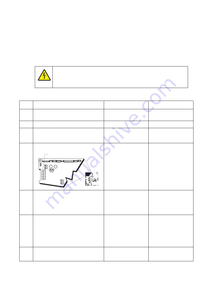
Check the system board for +5 V dc between
JLVPS2 pin 1 and ground.
Is the voltage correct?
Replace the system board.
See
“System board
removal” on page 4-139
.
Go to step 4.
4
Is the JLVPS2 cable correctly installed at
JLVPS2 on the system board?
Go to step 5.
Reseat the JLVPS1 cable.
5
Turn the printer off. Disconnect the JLVPS2
cable from the system board. Turn the printer
on, and then measure the voltage between
the JLVPS2 cable pin 1 and the JLVPS2
pin 14 (black wire).
Does this measure approxi5 V dc?
Go to step 6.
Replace the LVPS. See
“Low-voltage power
supply (LVPS) removal”
on page 4-98
.
6
1. Turn the printer off.
2. Disconnect the cables in J5, JCARTS1,
JCARTS2, JDVR1, JFDPCK1, JFUSER1,
JINT1, JOPT1, and JTLBT1.
3. Connect the JLVPS2 cable to the system
board.
4. POR the printer.
Does the printer still appear dead?
Contact your next level of
support.
Go to step 7.
7
1. Connect one cable at a time, and POR the
printer.
2. Is the printer dead?
The part connected to that
cable is faulty. Replace the
failing part.
Connect another cable and
continue with this step.
CAUTION
When you see this symbol, there is a danger from hazardous voltage in the area of the product
where you are working. Unplug the product before you begin, or use caution if the product
must receive power in order to perform the task.
1
JSB1
JBIN1
JFAN1
JFUSER1
JBOR1
JHVPS1
JMIRR1
JBLW1
JCVR1
JLVPS2
JCARTP1
JCARTS1
JCARTS2
JCARTP2
JDVR1
JTPS1
JOPT1
JFDS1
JINT1
JFDPCK1 JTRAY1 JSEC1
JDX1
JT12
J5
JDIMM1
JOPP1
JT1
JUSB1
JBOOT1
JFMUSB1
J49
JTWF1
JTDBUG1
1
1
1
1
1
1
1
1
1
1
1
1
1
1
1
1
1
1
1
1
1
1
1
1
1
JTLBT1
JPH1
F5
F6
F7
F9
F10
F12
F13
F14
1
1
J10
1
1
A
Содержание C734 series
Страница 13: ...Notices and safety information xiii 5026 ...
Страница 14: ...xiv Service Manual 5026 ...
Страница 170: ...2 136 Service Manual 5026 ...
Страница 255: ...Repair information 4 39 5026 11 Press the two tabs F to separate the right cover from the rear right cover F ...
Страница 284: ...4 68 Service Manual 5026 7 Remove the two screws G 8 Remove the duplex reference edge guide assembly G ...
Страница 288: ...4 72 Service Manual 5026 12 Remove the seven screws M securing the EP drive ...
Страница 339: ...Repair information 4 123 5026 13 Remove the three printhead mounting screws D ...
Страница 346: ...4 130 Service Manual 5026 f Scroll down to Quick Test and press Select A page similar to this one prints ...
Страница 395: ...Connector locations 5 1 5026 5 Connector locations Locations ...
Страница 408: ...7 2 Service Manual 5026 Assembly 1 Covers ...
Страница 410: ...7 4 Service Manual 5026 Assembly 2 Front ...
Страница 412: ...7 6 Service Manual 5026 Assembly 3 Right 1 2 3 4 5 6 ...
Страница 414: ...7 8 Service Manual 5026 Assembly 4 Rear ...
Страница 422: ...7 16 Service Manual 5026 Assembly 10 Optional high capacity input option HCIT 4 2 1 6 5 7 8 11 12 10 13 14 3 9 ...
Страница 424: ...7 18 Service Manual 5026 Assembly 11 Options and features ...
Страница 426: ...7 20 Service Manual 5026 ...
Страница 436: ...I 10 Service Manual 5026 ...


