background image

34 

48D0586

GLASS REPLACEMENT 

1.   Put  on  gloves.  Remove  frame  from  insert 

by releasing two hooks on bottom of insert 
and lifting the door up and off the unit. 

See 

Figure 44. 

3.  Carefully remove broken glass.

4.  Wrap new glass pane with tadpole gasket. 

Make  sure  you  have 

1

/

4

"  overlap  on  each 

side.

5.  Place new glass in frame.  


6.  Slide door back down onto insert and fasten 

two clamps. 

See Figure 45. 

Always  use  gloves  when  handling 
broken glass. 

C

A

U

T

IO

N


Make  sure  the  glass  panel  edges 
do  not  touch  any  metal  parts  during 
thermal expansion. 

W

A

R

N

IN

G

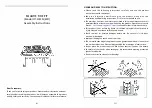
Figure 44 - Removing Door from Hinges 

Figure 45 - Replacing Glass (Inside of Frame Shown) 

NOTE:   Use only original Lexington Forge 

replacement parts.

Frame 


Glass Frame

Gasket

Glass 

Содержание ASHTON AI31DVC

Страница 1: ...age Refer to this manual For assistance or additional information consult a qualified installer service agency or the gas supplier This appliance is only for use with the type of gas indicated on the...

Страница 2: ...ing On Off Switch 26 Door Installation 27 Filigree Installation 28 Operating Instructions 29 What To Do If You Smell Gas 29 Lighting Pilot for the First Time 29 Lighting Pilot 30 Lighting Burner 31 To...

Страница 3: ...sealed If this unit is not properly installed by a quali ed service person with glass door properly seated and sealed combustion leakage can occur CARBON MONOXIDE POISONING Early signs of carbon monox...

Страница 4: ...CSA C22 1 16 Do not obstruct the ow of combustion and ventilation air in any way Provide adequate clearances around air openings into the combustion chamber along with adequate accessibility clearance...

Страница 5: ...ppliance is mobile home approved The appliance must be prop erly connected to a venting system PRODUCT SPECIFICATIONS The ef ciency rating of this appliance is a product thermal ef ciency rating deter...

Страница 6: ...W C 10 Maximum Supply Pressure 10 5 Maximum Supply Pressure 13 Minimum Supply Pressure 4 5 Minimum Supply Pressure 11 NOTE Ashton AI31 model insert works without any electrical supply Blower must have...

Страница 7: ...ck height Q N Depth of insert Q Insert back height AI31 FIREPLACE FIREPLACE MINIMUM OPENING A 235 8 601mm D 161 2 418mm B 291 4 743mm E 7 179mm C 26 660mm F 263 4 680mm G 181 8 459mm H 181 8 460mm I 2...

Страница 8: ...Before installing the gas replace insert consider the functioning needs of the replace Con rm the size of the replace cavity the design of the chimney and the availablility of the gas supply and elect...

Страница 9: ...e than 3 4 from the facing If it does it is considered a mantel and must meet the mantel requirements shown above HEARTH REQUIREMENTS The insert must be installed on a non combustible hearth extending...

Страница 10: ...eater may be placed in a bedroom Please be aware of the large amount of heat this appliance produces when determining a location 546mm The gas line should be installed prior to insert placement Run th...

Страница 11: ...Fireplace Zero Clearance Requirements IMPORTANT Please review the following carefully It is normal for inserts fabricated of steel to give off some expansion and or contraction noises during the start...

Страница 12: ...kit instructions Only a quali ed installer service person should install venting system The installer must follow these safety rules Wear gloves and safety glasses for protection Use extreme caution...

Страница 13: ...TK33A ALTITUDE CONSIDERATIONS This heater has been tested at altitudes ranging from sea level to 4 500 feet USA 0 2000 feet Canada In this testing heater with standard ori ce burns correctly with just...

Страница 14: ...Any cracks or damage inside chimney must be repaired The block off plate AI31AK33A must seal intake to the chimney space so that air is drawn down chimney for combustion air Block off Plate AI31AK33A...

Страница 15: ...ent Figure 12 Temporarily attach ex vent to top of chimney Leave some extra slack in ex vent 5 Slide insert into place Guide the manifold over the insert until it is fully in place Figure 13 6 Remove...

Страница 16: ...et and rebox exhaust hole 4 Pull manifold down to rebox See Figure 15 5 Attach clamp to manifold with hex nut Tighten nut with wrench See Figure 16 Figure 14 Lining up Metal Ring of Exhaust Pipe with...

Страница 17: ...olt hole in baf e over stud Thread acorn nut in place See Figure 17 7 Attach front baf e to top of rebox with ve 5 hex had sheet metal screws See Figure 17 Figure 17 Attaching Baffle to Top of Firebox...

Страница 18: ...e installing insert and burner system make sure you have the items listed below External regulator supplied by installer Tee joint Piping check local codes Pipe wrench Sealant resistant to propane LP...

Страница 19: ...own in Figure 19 Locate sediment trap drip leg where it is within reach for cleaning Install in piping system between fuel supply and burner system Locate sediment trap drip leg where trapped matter i...

Страница 20: ...and water solution or a gas sniffer 4 To adjust ame height turn HI LO knob to HI to get maximum pressure to burner Turn HI LO knob to LO to get minimum pressure 5 To check gas pressures at valve turn...

Страница 21: ...power supply or performing service All wiring shall be in compliance with all local city and state codes The appliance when installed must be electrically grounded in accordance with local codes or i...

Страница 22: ...ceramic fibers After handling the logs wash your hands gently with soap and water to remove any traces of bers The positioning of the logs is critical to the safe and clean operation of this heater So...

Страница 23: ...t base log 3 to the right of rear log 1 See Figure 24 6 Place left center log 4 on top two pins next to left base log 2 Line up hole in bottom left center log 4 with pin on burner See Figure 25 7 Set...

Страница 24: ...op log 6 on cutout of right base log 3 Line up hole in bottom or right top log 6 with pin on right center log 5 See Figure 27 9 Lay top Y log 7 across rear log 1 and left center logs 4 Place Y log 7 o...

Страница 25: ...p rock wool ember material into dime sized pieces Place evenly across burner surface and mesh of grate See Figures 29 and 30 Do not exceed 1 depth of coverage Lightly cover the airspace between logs a...

Страница 26: ...igure 31 3 If installing double doors install magnetic L bracket to bottom of surround with two 4 screws and 4 nuts provided See Figure 31 Magnetic L Bracket Magnets Screws Surround Install On Off Swi...

Страница 27: ...fore lighting the heater Any fingerprints left on the facing will be permanent when heater is lit NOTICE DOOR INSTALLATION INSTALLING DOORS Slide one door onto hinges Repeat for other door See Figure...

Страница 28: ...on the facing will be permanent when heater is lit NOTICE FILIGREE INSTALLATION INSTALLING FILIGREE FACING 1 Line up four 4 screw holes on ligree facing with four 4 screw holes on surround See Figure...

Страница 29: ...or explosion D Do not use this appliance if any part of it has been under water Immediately call a quali ed service tech nician to inspect the appliance and to replace any part of the control system a...

Страница 30: ...rol has an interlock device that does not allow the lighting of the insert up to the moment the safety device of the flame has not interrupted the gas flow After that period of time when the magnet is...

Страница 31: ...ockwise to the ON position See Figure 36 It will take less than four 4 seconds for the burner to ignite PILOT POSITION Depress and turn knob to pilot position to keep burner off while maintaining the...

Страница 32: ...typical pilot ame Let glass cool before cleaning Do not clean glass when it is hot Damage could occur CAUTION Make sure the gas valve knob is in the OFF position Wait at least five 5 minutes before s...

Страница 33: ...altitude as follows Figure 42 Pull Down Adjustment Knob to Open Air Shutter Figure 43 Push Up Adjustment Knob to Close Air Shutter To increase air mixture pull down the adjustment knob located behind...

Страница 34: ...you have 1 4 overlap on each side 5 Place new glass in frame 6 Slide door back down onto insert and fasten two clamps See Figure 45 Always use gloves when handling broken glass CAUTION Make sure the...

Страница 35: ...le and touch top of thermocouple See Figure 46 If not contact dealer for service 2 Turn gas control knob to OFF position to shut off gas to heater See step To Turn Off Gas page 31 Let heater cool for...

Страница 36: ...not formed Replace glass and glass frame if damaged 6 Inspect area behind access door Clean if necessary Check gas control valve and all gas lines If damaged do not use heater Contact your dealer 7 S...

Страница 37: ...operation after servicing CAUTION White Hi Temp NOTE Unplugpowercordbeforeservicing The blower is attached to insert bottom and back with Velcro To remove blower for servicing pull away from Velcro a...

Страница 38: ...38 48D0586 REPLACEMENT PARTS 6...

Страница 39: ...13 Hi Lo Knob Extension 1 43D0095 43D0095 14 Knob Extension ON OFF 1 43D0094 43D0094 15 Ignitor Battery Module 1 45D0077 45D0077 16 Ignitor Wire Switch 1 45D0078 45D0078 17 ON OFF Wire Harness 1 48D01...

Страница 40: ...tor connections are good but there is no spark 3 Check for spark arcing from the elec trode to pilot Adjust and retighten 1 Check for proper connection of thermo couple to rear of valve 2 Bleed line C...

Страница 41: ...THE INSTALLER FOR WARRANTY PURPOSES AND FUTURE REFERENCE LEXINGTON FORGE Model _____________________________ Name of Owner Name of Installer Address Address Phone Phone Name of Dealer Address Phone M...

Страница 42: ...42 48D0586 NOTES...

Страница 43: ...48D0586 43 NOTES...

Страница 44: ...thorized service center shipping damage damage from improper use or neglect installation damage damage from unauthorized service incidental or consequential damage or negative pressure caused by mecha...

Отзывы: