Page 5 of 11
PK-A3188-10-00-0B
CONFIGURATIONS
MOUNTING INSTRUCTIONS
1) Determine the location to mount the enclosure. Use the following considerations in selecting a mounting location:
a) Appropriate mounting base per applicable codes and Authority Having Jurisdiction (AHJ)
b) Space around the enclosure to open the door and route patch cables.
c) Adequate space above or below the enclosure to maintain industry standard bend radius compliance of all
cables entering the enclosure.
2) If using the large enclosure in the splice only configuration, install the splice tray hardware before mounting the
enclosure.
3) Using a level, place the enclosure at the target mounting location and mark the four mounting hole positions.
4) Install the top two screws and verify the enclosure is level during final tightening of screws.
5) Install the bottom two screws.
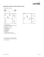
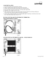
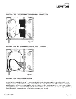
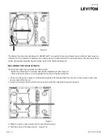
There are four possible configurations using the small and medium enclosures.
1) Field or pre-terminated cabling used with SDX adapter plates
2) Pigtail splicing used with SDX adapter plates
3) Pigtail splicing used with Splice modules
4) Use with pre-terminated MTP cabling and SDX cassettes or SDX to HDX adapter brackets
See the Installation section for diagrams of each configuration.
GROMMET PREPARATION AND USE
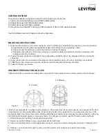
Cable Grommets are provided and designed for use at both trunk and patch cord entrance points to the enclosure.
There are several options in configuring the grommets. When patching, it is recommended to cut a channel at the front
of the grommet to easily install patch cords. When routing trunks it may be desired to cut a channel at the rear of the
grommet to allow for grommet removal for adding additional trunk cables. Grommet pass through material can either be
slit to limit dust and water egress or removed entirely. To configure a grommet, use the following cutting methods:
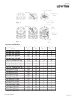
1) Determine required opening in cable entrance grommet
2) Determine whether slitting or removing material will be performed
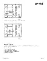
3) Using a sharp-edged tool, cut the appropriate opening in using the scored marking lines as shown in figures 2 and
3:
4) Optional – cut a channel through the outer wall of the grommet for either trunk or patch cord routing.
Figure 1
For Small
For Medium
Содержание Opt-X 5WMED-04C
Страница 12: ...PK A3188 10 00 0B Print on both sides ...


