Leuze MSI-SR-2H1 Series Скачать руководство пользователя страница 6


Leuze electronic GmbH + Co. KG 

In der Braike 1 D-73277 Owen

We reserve the right to make changes 

[email protected]  •  www.leuze.com 

Tel. +49 (0) 7021 573-0

03/2020 - 50134631-02 - 6/20 
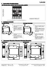
 

4


Function chart 

A1/A2/LED power supply 
Two-hand pushbutton T1 
Two-hand pushbutton T2  

Synchronous monitoring 


11 - 14 enable branch, LED.K1 

11 - 12 signalling branch 


t

A

 = response time 

t

R

 = release time 

t

W

 = recovery time 

t

S

 = synchronous monitoring time 


(1) Enable for synchronous operation 

(2) No re-enable if operation is interrupted  

(3) No enable as recovery time t

W

 is too short  

(4) No enable as synchronous monitoring time t

S

is too long


5


Technical data 

Function 

Two-hand monitoring relay

Function indicator 

2 LEDs, green

Version 

24 V AC/DC

Power circuit 

Rated voltage U

N

 A1, A2 

24 V AC/DC

Operating voltage range U

B

: 0.85 - 1.1 × U

N

20.4 to 26.4 V AC/DC

Rated power   (max) 

2 VA / 1 W  

(2.3 VA / 1.3 W)

Rated frequency  

50-60 Hz

Residual ripple 

2.4 V

SS

Electrical isolation between supply and control circuits

No

Control circuits 

T11

T12

T13 

Rated output voltage 

24 V DC

Input current 

2.5 mA

25 mA 

Max. peak current 

3 mA

60 mA 

Response time t

A


< 20 ms

Recovery time t

W


> 250 ms

Release time t

R


< 20 ms

Synchronous time monitoring t

S


500 ms

Max. line resistance per channel 

(5 + (1.176 × U

B

/ U

N

- 1) × 100) 

Output circuits  

Enabling current path 11-14

Signalling current path 11-12 

Switching function 

Changeover contact 

(NO contact)

Changeover contact  

(NC contact)

Conditional short-circuit current 

350 A 

300 A

Contact material 

Ag alloy

Rated switching voltage 

230 V AC

Max. thermal permanent current I

TH


5 A

Utilisation category 

AC-15: U

e

230 V, I

e

3 A

DC-13: U

e

24 V, I

e

2 A

Short circuit protection 

4 A class gG fuse, fuse integral 

< 1

00 A²s

Mechanical service life 

10

7

switching cycles

General data 

Air gap and creepage paths between the circuits

EN 60664-1  (pollution degree  2)

Protection class according to EN 60529 

IP40/IP20 (case/terminals)

Ambient operating temperature 

- 25 to +55 ℃ 

Storage temperature 

- 25 to +75 ℃

Weight 

100 g

Standards 

EN ISO 13849-1, EN 62061, ISO 13851:2019

Terminal and connection data 

Screw terminals

(1 clamping point per contact)

Spring-loaded terminals 

(2 clamping points per contact) 

Single-core or finely stranded  

1× 0.2 - 2.5 mm²

2× 0.2 - 1.0 mm²

2× 0.2-1.5 mm² 

Finely stranded with wire-end ferrule 

1× 0.25 - 2.5 mm²

2× 0.25 - 1.0 mm²

2× 0.25 - 1.5 mm²  

AWG conductor size (only use Cu wires)

26 - 14 

24 - 16

Maximum tightening torque 

0.5 - 0.6 Nm (5 - 7 lbf-in)

Stripping length 

7 mm 

7 mm


Содержание MSI-SR-2H1 Series

Страница 1: ...ge oder Demontage folgende Sicherheitsma nahmen durch 1 Schalten Sie das Ger t die Anlage vor Beginn der Arbeiten spannungsfrei 2 Sichern Sie die Maschine Anlage gegen Wiedereinschalten 3 Stellen Sie...

Страница 2: ...hlie lich der Freigabestrompfad 11 14 zu verwenden Der Meldestrompfad 11 12 ist lediglich f r nicht sicherheitsgerichtete Aufgaben zul ssig Das Betreiben des Ger tes au erhalb der Spezifikation kann z...

Страница 3: ...itzenstrom max 3 mA 60 mA Ansprechzeit tA 20 ms Wiederbereitschaftszeit tW 250 ms R ckfallzeit tR 20 ms Synchronzeit berwachung tS 500 ms Max Leitungswiderstand pro Kanal 5 1 176 UB UN 1 100 Ausgangsk...

Страница 4: ...fore starting installation assembly or dismantling 1 Disconnect the device the system from the power supply before starting work 2 Secure the machine system against being switched on again 3 Confirm t...

Страница 5: ...y be used to enabled hazardous movement The current signalling path 11 12 is only permitted for non safety related tasks Operating the device other than specified can result in malfunctions or destruc...

Страница 6: ...ery time tW 250 ms Release time tR 20 ms Synchronous time monitoring tS 500 ms Max line resistance per channel 5 1 176 UB UN 1 100 Output circuits Enabling current path 11 14 Signalling current path 1...

Страница 7: ...travaux mettre le module l installation hors tension 2 Prot ger la machine l installation contre toute remise en marche intempestive 3 S assurer de l absence de tension 4 Mettre les phases la terre e...

Страница 8: ...du courant de signalisation 11 12 est uniquement autoris pour les t ches non orient es vers la s curit L exploitation du module en dehors de la sp cification peut entra ner des dysfonctionnements ou u...

Страница 9: ...de pointe max 3 mA 60 mA Temps de r ponse tA 20 ms Temps de r excitation tW 250 ms Temps de retomb e tR 20 ms Surveillance de synchronisation tS 500 ms R sistance de ligne max par canal 5 1 176 UB UN...

Страница 10: ...gio mettere in atto le seguenti misure di sicurezza 1 Disinserire il dispositivo l impianto dalla tensione prima dell inizio dei lavori 2 Assicurare la macchina l impianto contro la riattivazione acci...

Страница 11: ...e il circuito di abilitazione 11 14 Il circuito di segnalazione 11 12 consentito solamente per operazioni non finalizzate alla sicurezza L utilizzo dell apparecchio al di fuori delle specifiche pu pro...

Страница 12: ...20 ms Tempo di ripristino tW 250 ms Tempo di rilascio tR 20 ms Monitoraggio tempo sincrono tS 500 ms Resistenza linea max per canale 5 1 176 UB UN 1 100 Circuiti di uscita Circuito di abilitazione 11...

Страница 13: ...rabajos de instalaci n montaje o desmontaje 1 Desconecte el aparato la instalaci n de la red el ctrica antes de comenzar los trabajos 2 Asegure la m quina instalaci n contra una reconexi n de corrient...

Страница 14: ...nea de contactos de se alizaci n 11 12 no est autorizada para funciones orientadas a la seguridad La utilizaci n del aparato m s all de las especificaciones puede conllevar fallos en el funcionamient...

Страница 15: ...ta m x 3 mA 60 mA Tiempo de reacci n tA 20 ms Tiempo de recuperaci n tW 250 ms Tiempo de desconexi n tR 20 ms Control del tiempo de sincronizaci n tS 500 ms Resistencia de l nea m x por canal 5 1 176...

Страница 16: ...uck in Pfeilrichtung Ger t auf die Hutschiene aufschnappen DE 3 Ger t in Pfeilrichtung herunterdr cken 4 Im heruntergedr ckten Zu stand Ger t in Pfeilrichtung aus der Verrastung l sen und von der Huts...

Страница 17: ...apparecchio alla barra DIN 2 Esercitando una leggera pressione in direzione della freccia fare scattare l apparecchio sulla barra DIN IT 3 Premere l apparecchio verso il basso in direzione della frec...

Страница 18: ...Leuze electronic GmbH Co KG In der Braike 1 D 73277 Owen We reserve the right to make changes info leuze de www leuze com Tel 49 0 7021 573 0 03 2020 50134631 02 18 20...

Страница 19: ...Leuze electronic GmbH Co KG In der Braike 1 D 73277 Owen We reserve the right to make changes info leuze de www leuze com Tel 49 0 7021 573 0 03 2020 50134631 02 19 20...

Страница 20: ...Leuze electronic GmbH Co KG In der Braike 1 D 73277 Owen We reserve the right to make changes info leuze de www leuze com Tel 49 0 7021 573 0 03 2020 50134631 02 20 20...

Отзывы: