Electrical Connection
Leuze
electronic
94
Technical Description BCL 90
Leuze electronic
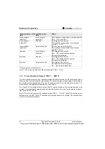
Table 7.19:Function combination of the switched inputs SE 2 … SE 6
7.5.7 Connect Switched Outputs "SWO 1 … SWO 4"
The four switched outputs can be individually assigned different functions of the result status output.
When an event occurs during the read process, the switched output corresponding to this particular
event will become energised after the end of the reading cycle for the selected pulse duration. The
pulse duration can be adjusted separately for each output.
The "Result" LED is coupled with the output "SWO 2" and is switched on in the operating mode "read
operation" for the adjusted pulse duration and selected function of the result status display (base set-
ting: "Good Read", 100 ms).
Figure 7.6 shows the circuitry of the switched outputs "SWO 1 … SWO 4". Table 7.20 contains the pin
assignment on the BCL. Table 7.21 describes the characteristics for the outputs. The characteristics
of the four outputs are the same.
Parameterization of the switched inputs
Effect
SE 5
SE 6
Focus position
switching
1)
Focus position
switching
1)
SE 5 switches focus position in combination with
SE 2 … SE 4 and SE 6
Focus position
switching
1)
One-shot
SE 6 triggers the one-shot
SE 5 switches focus position in combination
with SE 2 … SE 4
Focus position
switching
1)
Increment counter
SE 6 receives increment signals
SE 5 switches focus position in combination
with SE 2 … SE 4
One-shot
Focus position
switching
1)
SE 5 triggers the one-shot
SE 2 ... SE 4 switches focus position
SE 6 remains ineffective
One-shot
One-shot
SE 6 triggers the one-shot
SE 2 ... SE 4 switches focus position
SE 5 remains ineffective
One-shot
Increment counter
SE 5 triggers the one-shot
SE 6 receives increment signals
SE ... SE 4 remains ineffective
1)
varying with the cross-reference list
Buy: www.ValinOnline.com | Phone 844-385-3099 | Email: [email protected]


