Lesco 708686 Скачать руководство пользователя страница 6

6

LESCO

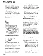
the turnbuckle at the top of the long control rod on
the side of the mower which seemed to creep must
be adjusted. Loosen the top and bottom nut on the
turnbuckle and adjust until the drive wheel stops
moving. Then retighten the top nuts.

7. The short traction/steering control rods which run

down from the traction/steering levers on each side
of the handle assembly should initially be adjusted
so that when the ground speed control levers are in
neutral and the traction/steering levers are in the
neutral lock position, the mower stands still with
the engine running. If the mower starts to creep
forward or to the rear in this situation, then the rod
end bearing at the bottom of the short control rod
on the side of the mower which seemed to creep
must be adjusted. Remove the hairpin holding the
long control rod in place in the rod end bearing,
remove the flat washer and pull the long control rod
from the rod end bearing. Loosen the lock nut and
adjust the rod end bearing ½ turn clockwise if the
creep was forward or ½ turn counter-clockwise if
the creep was to the rear. Tighten the lock nut,
replace the long control rod in the rod end bearing,
replace the flat washer and the hairpin.

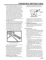
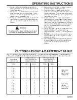
8. Adjusting the cutting height:  The mower is shipped

with the cutting height set at 3 inches
±1/4 inch depending on the air pressure in the
tires. To change the cutting height, blade spacers
and/or caster spacers must be moved according to
the table on page 6.

9. Lubricate all fittings listed in the maintenance

section.

C. Break-ln and Operation.

1. Make certain you thoroughly understand all of the

safety precautions before you attempt to operate
this machine.

2. Check the engine oil level. Fill to the proper level

with 10W40 or 10W30 engine oil rated for service SE or SF.

3. Check the hydraulic oil level. Remove the fill cap

and make sure the oil level is up to the bottom of
the strainer screen. Leave this air space for
expansion. If the oil level is low, fill with a good
grade of SAE 20W50 engine oil.

3. Move the mower outdoors. Check the engine

gasoline level. When filling the tank, stop when the
gasoline reaches one inch from the top. This space
must be left for expansion. Use fresh, clean,
unleaded, regular gasoline.

4. Move the mower to a “test area” where you can

operate the mower for about half an hour without
being disturbed.

5. To start the engine:

a.Move the ground speed control levers back to

the neutral position.

b.Disengage the blade clutch.
c.Place the neutral latch levers in the neutral lock

position.

d.Connect the spark plug wire.

e.Open the fuel shutoff valve.
f. Move the throttle lever to the “Choke” position.
g.Put the key in the ignition switch and turn the

switch to  “Start”. (Do not hold the key in the
start position for more than 10 seconds or you
may damage the starter.)

h.Set the throttle at 50% of full engine RPM and

allow the engine to warm up. Then, adjust the
throttle to 75% of full engine RPM.

6. After the engine has warmed up, shut off the

ignition and check the operation of the safety
switches. Make certain that the engine will not
start unless the ground speed control levers are in
neutral and the blade clutch is disengaged. If the
engine will start with either of the ground speed
control levers in any position other than neutral,
immediately shut off the engine and replace the
neutral safety switch operated by that lever under
the control panel. If the engine will start with the
blade clutch engaged, immediately shut off the
engine and adjust or replace, if necessary, the
blade safety switch mounted on the engine deck.
Start the engine and hold the left operator presence
lever down against the left handle and move the
left ground speed control lever out of neutral. Now
take your hand off the operator presence lever and
the engine should die. If it does not, immediately
shut off the engine and adjust or replace, if neces-
sary, the operator presence switch under the
control panel. Repeat this procedure moving the
right ground speed control lever out of neutral. If
the  engine does not die, immediately shut off the
engine and adjust or replace, if necessary, the
operator presence switch under the control panel.
Move both ground speed control levers into neutral,
restart the engine, hold the left operator presence
control down against the left handle and engage
the blade clutch. Now take your hand off of the
operator presence lever and the engine should die.
If it does not, immediately shut off the engine and
adjust or replace, if necessary, the operator
presence switch under the control panel. Disen-
gage the blade clutch.

7. Restart the engine.

8. Push the blade clutch lever forward until it engages

and the cutter blades start rotating.

9. Move the ground speed contol levers forward to

about one third of full speed.

OPERATING INSTRUCTIONS

   CAUTION

Set the ground speed control levers at no

more than one third full speed until you are

fully familiar with the operation of the mower.

Содержание 708686

Страница 1: ...HydroWalk Behind Commercial RotaryMowers 36 48 52 OPERATOR S MANUAL Standard andWide Track WT Models 708686 708687 708688 ...

Страница 2: ...vers 4 6 Traction Steering Levers 4 7 Neutral Latch Levers 5 8 Operator Presence Levers 5 9 FreewheelingValves 5 10 Hour Meter 5 B Initial Adjustments 5 C Break lnandOperation 6 Cutting Height Adjustment Table 7 Maintenance 8 A GeneralMaintenance 8 B Daily Maintenance After Mowing 8 C Maintenance Every 40 Hours 8 D LubricationChart 8 E EngineMaintenance 8 F Hydraulic System Maintenance 8 F MowerMa...

Страница 3: ... defeat their operation If the blade clutch is engaged or either of the ground speed control levers are out of the neutral position releasing both handles will shut off the mower s engine SAFETY PRECAUTIONS A General 1 Read this Operator s Manual before starting the mower Study the controls and learn the proper sequenceofoperation 2 Do not allow anyone to operate or maintain this machine who has n...

Страница 4: ...ed beneath the outer end of the right handle and a left hand lever located beneath the outer end of the left handle Each lever operates independently and when A Controls 1 Ignition and Start Switch Located in the center of the control panel between the handles This switch is an automotive key type ignition switch and a clockwise 45º turn closes the ignition circuit Turning the switch further again...

Страница 5: ... shut off the engine 9 Freewheeling pump relief Valves A T valve located on the side of each hydraulic OPERATING INSTRUCTIONS pump when opened will permit the mower to be pushed forward or pulled in reverse without the engine running To override the braking force of the hydraulic system turn each valve counter clockwise two turns move the mower as you wish and then turn each valve clockwise two tu...

Страница 6: ...round speed control levers back to the neutral position b Disengage the blade clutch c Place the neutral latch levers in the neutral lock position d Connect the spark plug wire e Open the fuel shutoff valve f Move the throttle lever to the Choke position g Put the key in the ignition switch and turn the switch to Start Do not hold the key in the start position for more than 10 seconds or you may d...

Страница 7: ... Check and adjust if necessary the tension of the deck drive belts and the pump drive belt as described in items 4 and 5 of the Initial Adjustment section 17 Readjust the traction steering control rods These adjustments are described in item 6 of the Initial Adjustment section 18 After the first full day of mowing all nuts bolt and screws should be rechecked for proper tightness and the belts shou...

Страница 8: ...t the spark plug wire 5 Wash the mower off with a water hose Be sure to clean out grass clippings from under the cutter deck and also under the deck cover Allow the mower to dry before storing 6 Check that the blade mounting bolts are tight 7 Check that the blades are sharp NOTE Never mow with dull blades 8 Check the fuel level the engine oil level and clean the cooling air intake the rotating scr...

Страница 9: ...O s Rotary MAINTENANCE Figure 2 Figure 4 Blade Grinder No 050655 or clamp the blade in a vise and using a flat mill file carefully file the cutting surface on each end of the blade to a sharp edge b Blades with severe nicks or dents that cannot be removed by filing should be replaced c After sharpening check the balance of the blade by placing the blade on the LESCO Blade Balancer fulcrum device N...

Страница 10: ...cuting the following procedures 1 Remove center mower deck cover by first removing two large wing nuts 2 Push against idler arm to release tension on the PTO belt For increased leverage a 3 8 inch square drive of a breaker bar can be placed in the 3 8 inch hole of the idler arm The breaker bar handle can be pushed to release tension on the PTO belt NOTE Be sure the narrow side of the belt is in th...

Страница 11: ... BELT See Figure 5 a Make sure the blade clutch is disengaged b Working under the engine deck take the long blade drive belt off of the engine pulley c Loosen the locknut holding the pump drive belt idler pulley in place and slide the pulley away from the pump drive belt d Remove the old belt and mount a new belt on the pulleys e Slide the idler pulley back onto the belt and tighten the locknut ho...

Страница 12: ...ed 0 1 0 050480 Short Drive Belt 48 fixed 0 1 0 068079 V Belt 52 long 0 0 1 068093 V Belt 52 Short 0 0 1 050441 V Belt 36 1 0 0 707579 Pump Drive Belt 1 0 0 707333 Pump Drive Belt 0 1 1 018969 Cartridge Hydraulic Oil Filter 1 1 0 050125 Blade 18 2 0 3 SUGGESTED ENGINE REPLACEMENT PARTS Air Filter Engine Oil Filter Air Filter Foam Wrap Spark Plug 707291 Kawasaki 15 0 HP 014888 703306 061660 703308 ...

Страница 13: ...13 LESCO This Page Intentionally Left Blank ...

Страница 14: ...14 LESCO This Page Intentionally Left Blank ...

Страница 15: ...15 LESCO This Page Intentionally Left Blank ...

Страница 16: ...E COURSE OF DEALING OR USAGE OF TRADE ARE HEREBY EXPRESSLY DISCLAIMED AND EXCLUDED 4 LIMITATION OF REMEDIES UNDER NO CIRCUMSTANCES EXCEPT TO THE EXTENT PROHIBITED BY APPLICABLE LAW SHALL LESCO BE LIABLE FOR ANY LOSS OR DAMAGE DIRECT OR INDIRECT SPECIAL INCIDENTAL OR CONSEQUENTIAL ARISING OUT OF THE USE OF OR INABILITY TO USE THIS EQUIPMENT INCLUDING BUT NOT LIMITED TO ANY CLAIM FOR LOSS OF PROFITS...

Отзывы: