6.2
The settings in the menu cannot be changed
Check in the menu whether the service mode has been activated.
6.3
Motor contactor monitoring
When the contactor is not requested by the control and nevertheless
a current is measurable on one or more phases, then the error
message “Contactor error” will appear in the display and the audible
alarm will sound.
7.0
Installation, electrical connection
7.1
Installation
The control unit
PS
MEGA
1
is placed in a control box that measures
250 x 225 x 115
mm (H x W x D) with screw fittings and air
connection). There are 4 drill holes on the switch cabinet for
mounting, which become visible when the cover is opened.
7.2
Hose attachment
As standard, a hose screw connection 8/6 mm is delivered for the
hose connection. Optionally, the switching device can be delivered
with other hose screw connections. The subsequent replacement of
the hose connection is also possible. The hose screw connection
must feature an internal thread of G1/8" towards the unit. During
replacement, it is important that a 14 mm spanner is used to secure
the corresponding nut. In any case, the threaded connection must be
used in combination with a suitable sealant.
7.3
Electrical connection power supply and pumps
The electrical connection must be performed by a qualified
electrician in accordance with the applicable VDE regulations.
HAZARD due to dangerous voltage!
Improper handling of electrical work may result in a risk of death
due to electrical voltage!
A time-lag fusing on the mains side of max.
3 x 16 A
must be
performed.
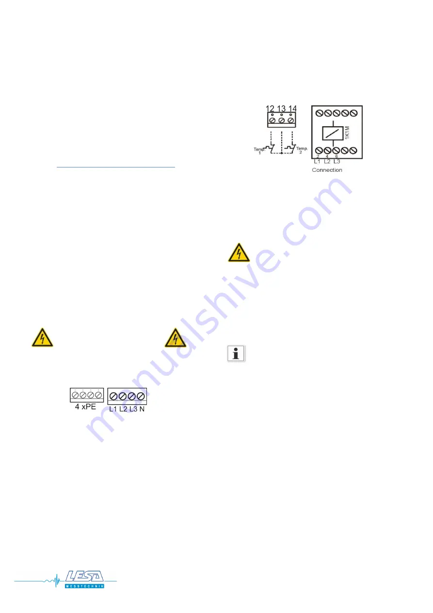
Mains connection (3~) PE , L1, L2, L3, N (image 1a in the
annex)
The connecting terminals have been designed for a max. cable cross
section of 4 mm². Attention must be paid that a right rotary field is
created. The terminals are labelled L1, L2, L3, N. The PE terminals are
implemented as a brass rail.
7.3.1
Connection of the pump:
The connections L1 L2 L3 of the pump are directly attached to the
motor contactor. The protective earth conductor is connected to the
remaining PE terminal. The bimetallic contact, which unlocks the
pump after it has cooled down, needs to be connected to terminal
12/13; the bimetallic contact that unlocks the pump after pressing
the “Quittung” button needs to be connected to terminal 13/14 on
the upper circuit board. (In case Temp.1 is not being connected,
thermal fault 1
needs to be deactivated in the menu).
To operate 1 ~ motors (230V AC)
a bridge between input
terminal N an L3 are necessary.
7.3.2
Power supply of the pumps (1~)
The pump is connected to contactor
T1 = L
and
T3 = N
7.3.3
Protective winding contacts
Regulator contact
Temp 1 / terminal 12/13
The pump is released automatically after cooling down.
Limiter contact
Temp 2 / terminal 13/14
The pump is only released after actuation of the acknowledge push
button.
This temperature monitoring must be used for pumps
located in the
EX area
.
When Temp. 1 is not used, then the function must be disabled in
the menu (see above chapter 5.2.7.).
When Temp. 2 is not used, then a wire jumper must be used from
terminal 13 to 14.
For pumps, in which the bimetallic contact has been switched in such
a manner that this directly interrupts the current of the pump, the
message
“Without load”
appears, when the bimetallic contact has
been triggered. The pump can only be taken into operation again
following the acknowledgement.
The inputs of the controls for the thermal errors are designed for the
evaluation of the protective winding contacts. Separate evaluation
devices must be used for motors with embedded temperature
sensors (e.g. PTC resistor) as thermal protection.
PS
MEGA
1
www.lesa.de
10


