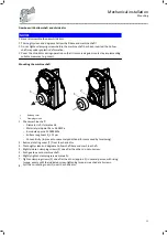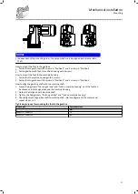
Gearbox with hollow shaft and shrink disc
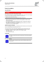
NOTICE
▶
Never disassemble the new shrink disc.
▶
Thoroughly clean and degrease hollow shaft bore and machine shaft!
▶
Do not tighten clamping screws before the machine shaft has been inserted, the hollow
shaft may undergo plastic deformation.
▶
Cover the shrink disc during operation so that it is secured against contact by implementing
suitable measures (e.g. cover).
Mounting the machine shaft
1
2
1
1
Rotating cover
2
Clamping screws
1
.
Check machine shaft
-
Diameter in fit tolerance h6
-
Material yield point Re ≥= 360 MPa
-
E-module approx. 210000 MPa
-
Surface roughness R
z
≤ 15 µm
-
Concentricity (to prevent unnecessary additional forces caused by tensioning)
2
.
Remove rotating cover
(1)
from the shrink disc
3
.
Thoroughly clean and degrease hollow shaft bore and machine shaft.
4
.
Slightly loosen clamping screws (2) one after the other, do not unscrew.
5
.
Push gearbox onto machine shaft.
6
.
Slightly tighten clamping screws manually.
7
.
Tighten clamping screws (2) one after the other (approx. 5) in several passes, with rising
torque, evenly until the indicated screw-tightening torque is reached at all screws.
8
.
Pull the co-rotating cover (1) over the shrink disc.
Mechanical installation
Mounting
25
Содержание g500-S
Страница 2: ......
Страница 23: ...Dimensions Dimensions are contained in the configuration document Mechanical installation Dimensions 23...
Страница 47: ...Template Dipsticks for G50BS122 100 mm 50 10 0 M1 M3 M4 M6 M2 M5 Maintenance Maintenance work 47...
Страница 48: ...Template Dipsticks for G50BS140 M1 M3 M6 M5 M2 M4 mm 100 50 10 0 Maintenance Maintenance work 48...
Страница 70: ......
Страница 71: ......


