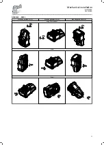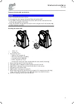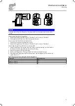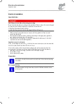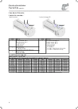
Position of the connections
4
4
3
3
2
1
Position
Meaning
1
Power connection
Brake connection
2
Feedback connection
Connection of temperature monitoring
3
PE connection
4
Large area shield contact.
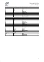
Terminal box, power
Contact
Name
Meaning
U1
L1
Motor winding phase
V1
L2
W1
L3
PE
PE
PE conductor
Terminal box, DC brake
Contact
Name
Meaning
BD1
+
Brake +
BD2
-
Brake -
Terminal box, resolver
Contact
Name
Meaning
B1
+Ref
Transformer windings (reference windings)
B2
-Ref
B3
+VCC ETS
Supply: Electronic nameplate (only for variant with electronic nameplate
ETS)
B4
+COS
Stator windings cosine
B5
-COS
B6
+SIN
Sine stator windings
B7
-SIN
B8
Not assigned
Electrical installation
Motor connection
Connection via terminal box
32
Содержание g500-S
Страница 2: ......
Страница 23: ...Dimensions Dimensions are contained in the configuration document Mechanical installation Dimensions 23...
Страница 47: ...Template Dipsticks for G50BS122 100 mm 50 10 0 M1 M3 M4 M6 M2 M5 Maintenance Maintenance work 47...
Страница 48: ...Template Dipsticks for G50BS140 M1 M3 M6 M5 M2 M4 mm 100 50 10 0 Maintenance Maintenance work 48...
Страница 70: ......
Страница 71: ......


