


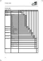


Rated data, LongLife design, IP54/55
Holding brake
06
08
Power input
180 V DC
W
20
25
Moment of inertia
kgcm²
0.15
0.61
Braking torque is static
Nm
4
8
Min. static braking torque tolerance
%
-25
-25
Max. static braking torque tolerance
%
35
35
Reversing cycles
15x 10
6
15x 10
6
Repetitive cycles
10x 10
6
10x 10
6
Maximum switching energy
J
3000
7500
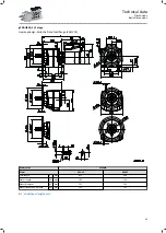
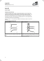
Manual release lever
When ordering, specify the position of the manual release lever (T, L, R or B).
Terminal box and manual release lever are not possible in the same position!
Δk
k
5
d
12
h
5
T
B
L
R
Motor
Brake size
Dimensions
k
5
Δ k
h
5
d
12
mm
MSEMABR063-42
06
178
29
107
13
MSEMABR080-32
08
224
27
116
13
Product extensions
Brakes
Spring-applied holding brake
103
Содержание g500-H
Страница 1: ...Mains operated geared motors g500 H helical geared motor Smart Motor m300 E Project planning EN...
Страница 2: ......
Страница 114: ......
Страница 115: ......
Страница 116: ...11 2021 2 0 www Lenze com...


