


506305-01
Page 25 of 36
Issue 0938
Thermostat
Install a room thermostat according to the instructions
furnished with it. Select a location on an inside wall that is
not subject to drafts, direct sunshine, or other heat sources.
The initial heat anticipator setting should be equal to the
total current draw of the control circuit.
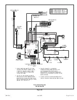
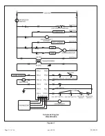
Low voltage thermostat connections are to be made to the
integrated ignition/blower control board as indicated on the
wiring diagram.
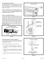
Humidifier
Terminals are provided on the integrated ignition/blower control
board for connection to a 120-volt humidifier. The “HUM” terminal
is energized whenever the thermostat calls for heat. Refer to furnace
wiring diagram for specific connection information.
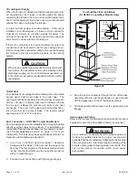
Continuous Low Speed Blower
If continuous blower operation on low speed is desired,
connect the lowest speed motor tap to the “CONT” terminal
on the integrated ignition/blower control board (refer to the
furnace wiring diagram.) The blower will operate on low
speed whenever main power is connected to the furnace,
except when it operates on heating or cooling speed during
thermostat call for heat or cooling.
This constant air
terminal is intended for low speed only.
If a motor is
wired for a higher speed, the increased amp draw could
cause the control board to fail and void the warranty.
Electronic Air Cleaner
Terminals are provided on the integrated ignition/blower
control board for connection of a 120-volt electronic air
cleaner. The “EAC” terminal is energized whenever the
thermostat is calling for heat, cooling, or continuous blower.
Refer to the furnace wiring diagram for specific connection
information.
Twinning
The integrated ignition/blower control board is designed to
permit “twinning” of furnaces (two furnaces connected to a
common supply and return air system, and controlled by
one thermostat). An accessory kit must be ordered from
the manufacturer. Specific wiring and operating instructions
are included with the kit.
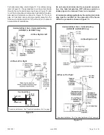
Each furnace must have its own dedicated vent system.
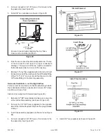
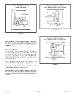
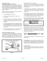
Filter Rack Mounting Hole
Screw
Filter Rack
Corner Embossments
Front of Cabinet
Filter Rack Installation
Figure 36
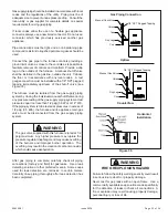
Bottom Filter Location
Upflow Models
Figure 37
Filter
Base
Side


