


506305-01
Page 19 of 36
Issue 0938
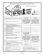
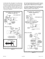
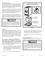
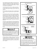
6.
From the tee, connect the drain to disposal area. The top
of the tee must be left open for proper condensate
drainage. The open end of the tee must be oriented so
that condensate does not run out of the opening.
7.
Remove 72" vinyl hose supplied with unit and cut in half.
Connect one end of the vinyl hose to the 3/8" barbed fitting
of the 2" x 2" x 1/2" tee in vent and the other end to the
3/8” barbed fitting on the drain trap assembly.
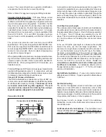
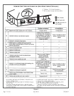
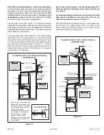
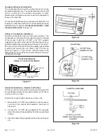
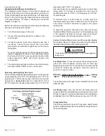
Horizontal Installation – Left to Right Airflow
Furnace must be mounted such that the side through which
the condensate will drain is elevated a minimum of 9" above
a surface such as a floor.
Install unit at a slight pitch forward (see Figure 26).
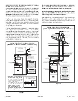
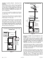
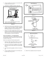
1.
Relocate 1/2" NPT plug installed on flue pan to one side
of the internal trap assembly (as shown in Figure 27).
2.
Connect the 1/2" NPT plug (supplied) to the opposite
side of the internal trap assembly from the plug installed
in Step 1.
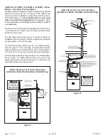
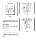
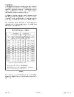
3.
Insert trap assembly (supplied) into flue pan (see Figure
28).
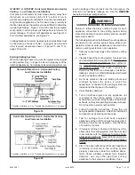
4.
Connect a length of 3/4" PVC pipe (3' minimum) to the
trap assembly (see Figure 29).
4.
Connect a length of 3/4" PVC pipe (3' minimum) to the
trap assembly (see Figure 25).
5.
Install 3/4" tee (supplied) as shown in Figure 25.
5.
Install 3/4" tee (supplied) as shown in Figure 29.
Figure 28
Install Trap Assembly
Completing Condensate
Drain Installation
3/4" Tee
3/8" Vinyl Hose
(supplied)
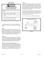
Be sure to avoid double-trapping the vinyl hose.
Hose must be installed as shown.
Figure 25
Figure 26
Tilt Unit Forward
Figure 27
Insert Plugs


