


506305-01
Page 24 of 36
Issue 0938
Electrical Wiring
The furnace must be grounded and wired in accordance
with local codes or, in the absence of local codes, with the
National Electrical Code ANSI/NFPA No. 70 (latest edition)
and/or CSA C22.1 Electrical Code (latest edition) if an
external electrical source is utilized.
In all instances, other than wiring for the thermostat, the
wiring to be done and any replacement of wire shall conform
with the temperature limitation for Type T wire –63°F (35°C)
rise.
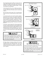
Connect a sufficiently sized wire with ground to the furnace’s
line voltage connections and ground lug. Refer to the furnace
rating plate for electrical characteristics to be used in sizing
field supply wiring and over-current protection.
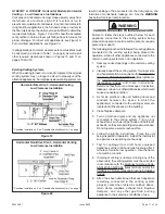
The line voltage supply should be routed through a readily
accessible disconnect located within sight of the furnace.
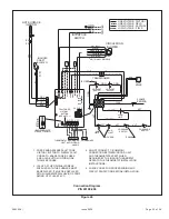
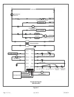
A junction box on the furnace side panel is provided for line
voltage connections. Refer to the furnace wiring diagram
for specific connection information.
Proper polarity of the supply connections (“HOT” and
“NEUTRAL”) must be observed to ensure that safety
controls provide the protection intended.
A connection to the ground lug and actual earth ground
(typically a ground stake or buried steel pipe) must be
maintained for proper operation.
Filters
Filters are not supplied with G1D93BC series furnaces.
G1D91BU, G1D91BT, G1D93BT AND G1D93BU Upflow
Models
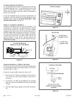
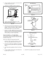
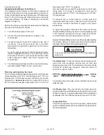
A filter rack and cleanable 16” x 25” x 1/2” filter are supplied
with the furnace. (Models designed for more than 1600 CFM
nominal air delivery include two of each.) The filter rack is
to be installed between the return air duct and the side of
the furnace. Refer to Figure 36 and the following instructions
to install the filter rack:
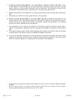
1. Using the corner embossments as a guide, mark and
cut a full-size opening in the side panel(s).
Risk of electrical shock. Disconnect electrical power at
the circuit breaker or service panel before making
electrical connections. Failure to disconnect power
supplies can result in property damage, personal injury,
or death.
WARNING
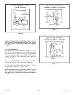
2. Using the filter rack as a template, mark and drill four
7/64” diameter screw holes in the side panel(s).
3. With the filter access opening toward the front of the
furnace, use sheet metal screws to fasten the rack(s) to
the side panel(s).
The filter slides in the rack from the front of the unit. Install
the filter(s) with the mesh side towards furnace.
Single side filter frame kit AFILTHA7 is available for single
side return air connection in installations requiring more than
1600 CFM nominal air delivery. Bottom return filter kit
AFILT529 is also available from the manufacturer.
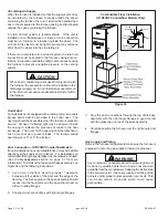
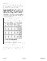
GID93BC Counterflow Models
Filters are not supplied with these furnaces, however, filters
must be used. It is the installer’s responsibility to install
properly sized filters in accordance with Table 3.
Other filter accessories are also available from the
manufacturer including a full line of indoor air quality
products. For information on these products, contact the
local distributor.
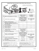
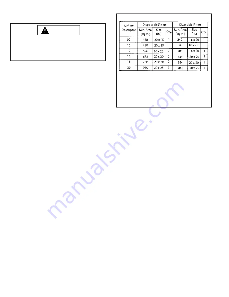
Table 3
Minimum Filter Requirements
1.
The Airflow Descriptor is the two digits following the “D” in the
model number.
2.
Areas and dimensions shown for cleanable filters are based
on filters rated at 600 feet per minute face velocity.
3.
Typical filter sizes are shown; however, any combination of filters
whose area equals or exceeds the minimum area shown is
satisfactory.


