Lenovo ThinsStation P320 Скачать руководство пользователя страница 112

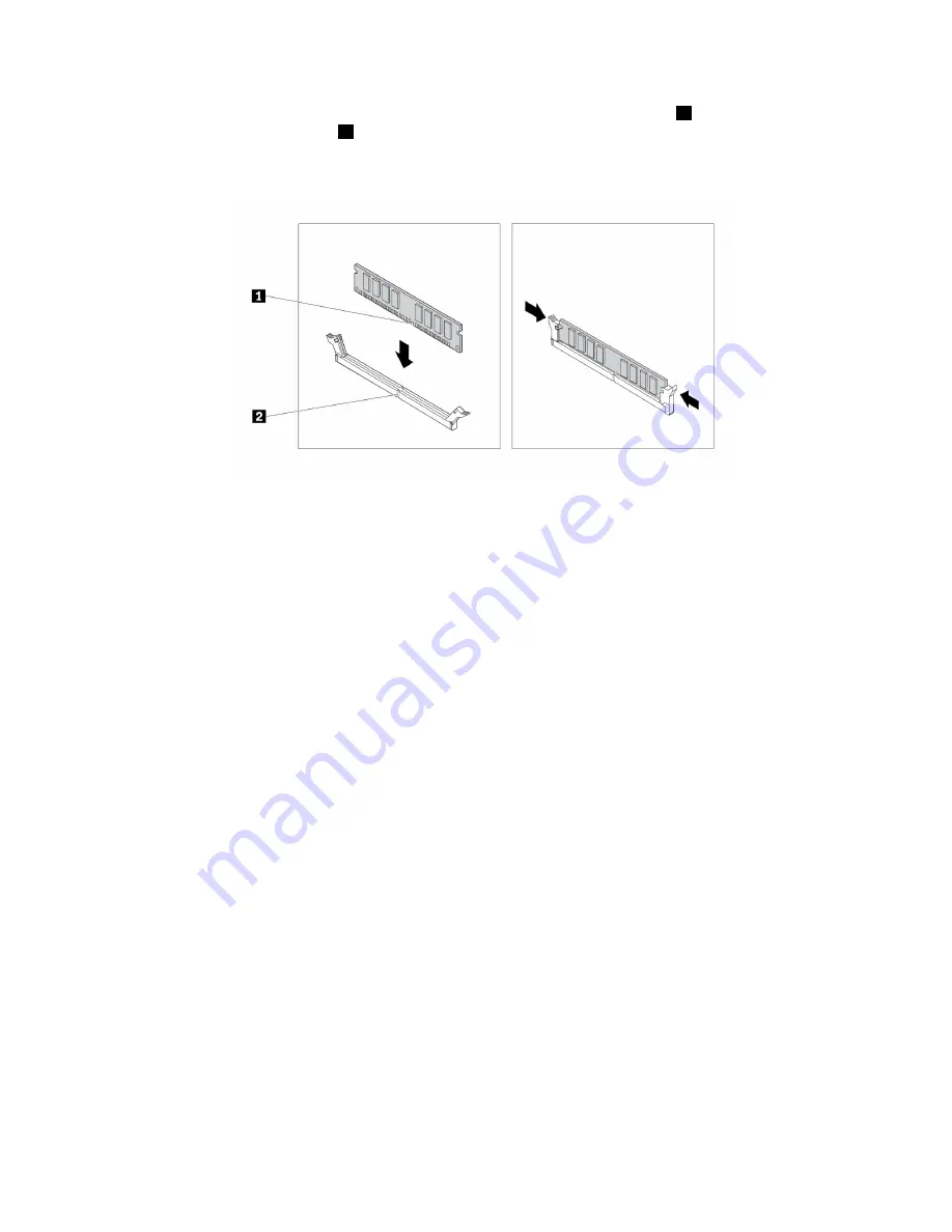
6. Position the new memory module over the memory slot. Ensure that the notch

1

on the memory

module is aligned with the key

2

in the slot. Push the memory module straight down into the slot until

the retaining clips completely close.

Figure 29. Installing a memory module

7. Reinstall the PCIe x16 graphics card if you have removed it.

What to do next:

• To work with another piece of hardware, go to the appropriate section.

• To complete the installation or replacement, go to “Completing the parts replacement” on page 166.

Optical drive

Attention:

Do not open your computer or attempt any repair before reading and understanding the Chapter

1 “Read this first: Important safety information” on page 1.

Note:

For some computer models, the optical-drive bay might be installed with an optical drive, a Multi-drive

Conversion Kit, or a Slim Optical Drive Adapter.

To install or replace an optical drive, do the following:

1. Prepare your computer. See “Preparing your computer and removing the computer cover” on page 91.

2. Remove the front bezel. See “Front bezel” on page 92.

3. Depending on whether you are installing or replacing an optical drive, do one of the following:

• If you are installing an optical drive, do the following:

a. Remove the metal static shield from the desired drive bay.

104

P320 Hardware Maintenance Manual

Содержание ThinsStation P320

Страница 1: ...P320 Hardware Maintenance Manual Machine Types 30BG 30BH and 30BR ...

Страница 2: ...safety information on page 1 and Appendix G Notices on page 189 First Edition April 2017 Copyright Lenovo 2017 LIMITED AND RESTRICTED RIGHTS NOTICE If data or software is delivered pursuant to a General Services Administration GSA contract use reproduction or disclosure is subject to restrictions set forth in Contract No GS 35F 05925 ...

Страница 3: ...Maintenance 51 Basic maintenance tips 51 Good maintenance practices 51 Keeping your computer current 52 Moving your computer 53 Chapter 5 Security 55 Locking your computer 55 Attaching a padlock 55 Attaching a Kensington style cable lock 56 Attaching a cable lock 57 Viewing and changing security settings in the Setup Utility program 57 Using passwords and Windows accounts 57 Using the cover presen...

Страница 4: ... 104 Device in the 5 25 inch flex module 107 Hard disk drive in the front access storage enclosure 119 Device in the Multi drive Conversion Kit 121 Battery 133 Front audio and USB assembly 135 Internal speaker 136 Thermal sensor 137 Cover presence switch 139 Power supply assembly 140 Heat sink and fan assembly 142 Microprocessor 143 System board 146 Primary hard disk drive 148 Secondary hard disk ...

Страница 5: ...ling information for Brazil 182 Battery recycling information for Taiwan 182 Battery recycling information for the European Union 183 Appendix E Restriction of Hazardous Substances RoHS Directive 185 Appendix F ENERGY STAR model information 187 Appendix G Notices 189 Appendix H Trademarks 191 Copyright Lenovo 2017 iii ...

Страница 6: ...iv P320 Hardware Maintenance Manual ...

Страница 7: ...oubleshoot problems Important This manual is intended only for trained service technicians who are familiar with ThinkStation computers Use this manual along with the advanced diagnostic tests to troubleshoot problems effectively Before servicing a ThinkStation computer be sure to read and understand Chapter 1 Read this first Important safety information on page 1 Copyright Lenovo 2017 v ...

Страница 8: ...vi P320 Hardware Maintenance Manual ...

Страница 9: ...ch can eventually result in overheating Ensure that all power cord connectors are securely and completely plugged into receptacles Do not use any power adapter that shows corrosion at the ac input pins or shows signs of overheating such as deformed plastic at the ac input or anywhere on the power adapter Do not use any power cords where the electrical contacts on either end show signs of corrosion...

Страница 10: ...afety device that is worn or defective Reinstall all covers correctly before returning the machine to the customer CAUTION Hazardous moving parts Keep fingers and other body parts away CAUTION Before you open the computer cover turn off the computer and wait several minutes until the computer is cool Electrical safety CAUTION Electrical current from power telephone and communication cables can be ...

Страница 11: ... approved probe leads and accessories for that tester Stand on suitable rubber mats obtained locally if necessary to insulate you from grounds such as metal floor strips and machine frames Observe the special safety precautions when you work with very high voltages these instructions are in the safety sections of maintenance information Use extreme care when measuring high voltages Regularly inspe...

Страница 12: ...ion Use a meter to measure third wire ground continuity for 0 1 ohm or less between the external ground pin and frame ground b The power cord should be the appropriate type as specified in the parts listings c Insulation must not be frayed or worn 4 Remove the cover 5 Check for any obvious alterations Use good judgment as to the safety of any alterations 6 Check inside the unit for any obvious uns...

Страница 13: ... can use coax or connector outside shells on these systems Use the round ground prong of the ac plug on ac operated computers Grounding requirements Electrical grounding of the computer is required for operator safety and correct system function Proper grounding of the electrical outlet can be verified by a certified electrician Safety notices multi lingual translations The caution and danger safe...

Страница 14: ...5C1566 or an equivalent type battery recommended by the manufacturer If your system has a module containing a lithium battery replace it only with the same module type made by the same manufacturer The battery contains lithium and can explode if not properly used handled or disposed of Do not Throw or immerse into water Heat to more than 100 C 212 F Repair or disassemble Dispose of the battery as ...

Страница 15: ...and the power switch on the power supply do not turn off the electrical current supplied to the device The device also might have more than one power cord To remove all electrical current from the device ensure that all power cords are disconnected from the power source 1 2 Chapter 1 Read this first Important safety information 7 ...

Страница 16: ...8 P320 Hardware Maintenance Manual ...

Страница 17: ...8 kg 37 lb 32 kg 70 5 lb 55 kg 121 2 lb 1 2 PERIGO A corrente elétrica proveniente de cabos de alimentação de telefone e de comunicações é perigosa Chapter 1 Read this first Important safety information 9 ...

Страница 18: ...aos dispositivos 3 Conecte os cabos de sinal aos conectores 4 Conecte os cabos de alimentação às tomadas 5 LIGUE os dispositivos 1 DESLIGUE Tudo 2 Primeiramente remova os cabos de alimentação das tomadas 3 Remova os cabos de sinal dos conectores 4 Remova todos os cabos dos dispositivos CUIDADO Ao substituir a bateria de lítio utilize apenas uma bateria com Número de Peça 45C1566 ou um tipo de bate...

Страница 19: ...te exposição direta ao feixe 18 kg 37 lb 32 kg 70 5 lb 55 kg 121 2 lb CUIDADO Utilize procedimentos de segurança para levantar equipamentos CUIDADO O botão de controle de alimentação do dispositivo e o botão para ligar desligar da fonte de alimentação não desligam a corrente elétrica fornecida ao dispositivo O dispositivo também pode ter mais de um cabo de alimentação Para remover toda a corrente ...

Страница 20: ...12 P320 Hardware Maintenance Manual ...

Страница 21: ...1 2 Chapter 1 Read this first Important safety information 13 ...

Страница 22: ...1 2 14 P320 Hardware Maintenance Manual ...

Страница 23: ...roduit ou des périphériques qui lui sont raccordés reportez vous aux instructions ci dessous pour connecter et déconnecter les différents cordons Connexion Déconnexion 1 Mettez les unités HORS TENSION 2 Commencez par brancher tous les cordons sur les unités 3 Branchez les câbles d interface sur des connecteurs 4 Branchez les cordons d alimentation sur des prises 5 Mettez les unités SOUS TENSION 1 ...

Страница 24: ... laser contiennent une diode à laser intégrée de classe 3A ou 3B Prenez connaissance des informations suivantes Rayonnement laser lorsque le carter est ouvert Evitez toute expositiondirecte au rayon laser Evitez de regarder fixement le faisceau ou del observer à l aide d instruments optiques 18 kg 37 lb 32 kg 70 5 lb 55 kg 121 2 lb ATTENTION Soulevez la machine avec précaution ATTENTION L interrup...

Страница 25: ...ind Zum Installieren Transportieren und Öffnen der Abdeckungen des Computers oder der angeschlossenen Einheiten die Kabel gemäß der folgenden Tabelle anschließen und abziehen Zum Anschließen der Kabel gehen Sie wie folgt vor Zum Abziehen der Kabel gehen Sie wie folgt vor 1 Schalten Sie alle Einheiten AUS 2 Schließen Sie erst alle Kabel an die Einheiten an 3 Schließen Sie die Signalkabel an die Buc...

Страница 26: ...er angegeben verwendet kann gefährliche Laserstrahlung auftreten VORSICHT Einige Lasergeräte enthalten eine Laserdiode der Klasse 3A oder 3B Beachten Sie Folgendes Laserstrahlung bei geöffneter Verkleidung Nicht in den Strahl blicken Keine Lupen oder Spiegel verwenden Strahlungsbereich meiden 18 kg 32 kg 55 kg ACHTUNG Arbeitsschutzrichtlinien beim Anheben der Maschine beachten ACHTUNG Mit dem Netz...

Страница 27: ...1 2 Chapter 1 Read this first Important safety information 19 ...

Страница 28: ...1 2 20 P320 Hardware Maintenance Manual ...

Страница 29: ...i installazione spostamento o apertura dei coperchi di questo prodotto o delle unità collegate Per collegarsi Per scollegarsi 1 SPEGNERE le apparecchiature 2 Innanzitutto collegare tutti i cavi alle unità 3 Collegare i cavi di segnale ai connettori 4 Collegare i cavi di alimentazione alla presa 5 Accendere l unità 1 SPEGNERE le apparecchiature 2 Innanzitutto rimuovere i cavi di alimentazione dalla...

Страница 30: ...ser contengono un diodo laser di Classe 3A o Classe 3B Tener presente quanto segue Aprendo l unità vengono emesse radiazioni laser Non fissare il fascio non guardarlo direttamente con strumenti ottici ed evitare l esposizione al fascio 18 kg 32 kg 55 kg ATTENZIONE Prestare attenzione nel sollevare l apparecchiatura ATTENZIONE Il pulsante di controllo dell alimentazione presente sull unità e l inte...

Страница 31: ...Chapter 1 Read this first Important safety information 23 ...

Страница 32: ...talación mantenimiento o reconfiguración de este producto durante una tormenta eléctrica Conecte todos los cables de alimentación a tomas de corriente debidamente cableadas y conectadas a tierra Cualquier equipo que se conecte a este producto también debe conectarse a tomas de corriente debidamente cableadas Siempre que sea posible utilice una sola mano para conectar o desconectar los cables de se...

Страница 33: ...vos PRECAUCIÓN Cuando sustituya una batería de litio utilice solamente una batería número de pieza 45C1566 u otra de tipo equivalente recomendada por el fabricante Si su sistema dispone de un módulo que contiene una batería de litio reemplácelo sólo con el mismo tipo de módulo del mismo fabricante La batería contiene litio y puede explotar si no se utiliza manipula o desecha correctamente No debe ...

Страница 34: ...N Adopte procedimientos seguros al levantar el equipo PRECAUCIÓN El botón de control de alimentación del dispositivo y el interruptor de alimentación de la fuente de alimentación no desconectan la corriente eléctrica suministrada al dispositivo Además el dispositivo podría tener más de un cable de alimentación Para suprimir toda la corriente eléctrica del dispositivo asegúrese de que todos los cab...

Страница 35: ...ns of your computer hardware Front view Note The computer hardware might look slightly different from the illustrations Figure 1 Front view 1 Optical drive eject close button 2 USB 3 0 connectors 2 3 Hard disk drive activity indicator 4 Power indicator 5 Power button 6 Microphone connector 7 Headset connector 8 Card reader available on some models 1 Optical drive eject close button Press the butto...

Страница 36: ...r is unresponsive you can turn off the computer by pressing and holding the power button for four or more seconds 6 Microphone connector Use this connector to attach a microphone to your computer when you want to record sound or if you use speech recognition software 7 Headset connector Use this connector to attach a headset to your computer 8 Card reader available on some models This is a 9 in 1 ...

Страница 37: ...connector 8 PCIe card area different cards provide different connectors 9 Audio line in connector 10 Optional serial connector 11 Cable lock slots 12 Padlock loop 13 Audio line out connector 14 Ethernet connector 15 PS 2 keyboard connector available on some models 16 Security lock slot 1 Power cord connector Connect the power cord to your computer for power supply 2 10 Serial connector Use this co...

Страница 38: ... Audio line in connector Used to receive audio signals from an external audio device such as a stereo system When you attach an external audio device a cable is connected between the audio line out connector of the device and the audio line in connector of the computer 11 Cable lock slots 2 Used to secure a cable lock For more information see Attaching a cable lock on page 57 12 Padlock loop Conne...

Страница 39: ...embly 2 Memory module 3 Optical drive available on some models 4 Card reader available on some models 5 Front audio and USB assembly 6 Front bezel 7 Front fan assembly available on some models 8 Hard disk drives 9 Graphics card available on some models 10 Cover presence switch also called intrusion switch available on some models 11 Rear fan assembly 12 Power supply assembly Major FRUs and CRUs Th...

Страница 40: ... might not be available Figure 4 Major FRUs and CRUs The following table lists the major FRUs shown in Figure 4 Major FRUs and CRUs on page 32 and identifies which FRUs are also self service CRUs or optional service CRUs Notes 32 P320 Hardware Maintenance Manual ...

Страница 41: ...ls Yes No 8 Microprocessor No No 9 Memory modules Yes No 10 Card reader No No 11 Front audio and USB assembly No No 12 Front bezel Yes No 13 Power button No No 14 Thermal sensor available on some models No No 15 Front Wi Fi antenna available on some models No No 16 Internal speaker No No 17 Front fan assembly available on some models No Yes 18 Hard disk drive or hybrid drive available on some mode...

Страница 42: ...DIMM2 8 Memory slot 3 DIMM3 9 Memory slot 4 DIMM4 10 Thermal sensor connector 11 10 pin power connector 12 Hard disk drive fan connector 13 4 pin SATA power connectors 14 Thunderbolt connector 15 Parallel connector 16 eSATA connector 17 SATA connectors 18 Power fan connector 19 USB hardware disable header 20 Front bezel connector for connecting LED indicators and the power button 21 Front USB 3 0 ...

Страница 43: ...ce an internal drive note the type and size of the drive that each bay supports and correctly connect the required cables Refer to the appropriate section in Chapter 9 Hardware installation and replacement on page 91 for instructions on how to install or replace internal drives for your computer The following illustration shows the locations of the drive bays Note The computer hardware might look ...

Страница 44: ...type and model information helps support technicians to identify your computer and provide faster service The following is a sample of the machine type and model label Figure 7 Machine type and model label Computer features For your specific computer model some features might vary or not apply Information about your computer To view basic information such as microprocessor and memory information a...

Страница 45: ...Advanced Technology Attachment SATA hard disk drive SATA hybrid drive available on some models SATA solid state drive available on some models PCIe solid state drive M 2 solid state drive available on some models To view the amount of storage drive space do the following 1 Depending on your Windows version do one of the following For Windows 7 Click the Start button to open the Start menu Right cl...

Страница 46: ...rive bays Memory slots Optical drive bays PCIe x1 card slots PCIe x16 card slot negotiable link width x4 x1 PCIe x16 graphics card slot graphics card available on some models For more information see Internal drives on page 35 and Parts on the system board on page 34 Power supply Your computer comes with one of the following power supplies 250 watt automatic 85 voltage sensing power supply 400 wat...

Страница 47: ...ed Technology Attachment SATA Redundant Array of Independent Disks RAID 5 arrays and SATA RAID 10 arrays on specific Intel chipset system boards to enhance hard disk performance Preboot Execution Environment PXE Preboot Execution Environment enables you to start computers using a network interface This manner is independent of starting computers from data storage devices such as the hard disk driv...

Страница 48: ...erating system has been certified or tested for compatibility check the Web site of the operating system provider Computer specifications This section lists the physical specifications for your computer Dimensions Width 175 mm 6 89 inches Height 376 mm 14 80 inches Depth 426 mm 16 77 inches Weight Maximum configuration as shipped 13 kg 28 66 lb Environment Air temperature Operating From 10 C 50 F ...

Страница 49: ...indows 10 Click the Start button to open the Start menu Then click the name of the desired program to launch the program 2 If the program name is not displayed on the Start menu access the program from Control Panel a Depending on your Windows version do one of the following For Windows 7 Click Control Panel on the Start menu For Windows 10 Right click the Start button to open the Start context me...

Страница 50: ... Lenovo PC Experience program helps you work more easily and securely The program provides easy access to Lenovo ThinkVantage Tools or Lenovo Tools important settings and information about your computer the Lenovo Support Web site and so on Lenovo ID Windows 10 The Lenovo ID program enables you to create and manage your Lenovo ID With a Lenovo ID you can connect to everything Lenovo through a sing...

Страница 51: ...fication area add the icon to the notification area See the Windows help system 2 Follow the instructions on the screen and the hover text to adjust the volume mute the speaker or unmute the speaker Using a disc This section provides instructions on how to use a disc and the optical drive Guidelines about using the optical drive When using the optical drive follow these guidelines Do not place the...

Страница 52: ...e drive 2 Carefully remove the disc from the tray 3 Press the eject close button again or gently push the tray forward to close the tray Note If the tray does not slide out of the drive when you press the eject close button turn off your computer Then insert a straightened paper clip into the emergency eject hole adjacent to the eject close button Use the emergency eject only in an emergency Recor...

Страница 53: ...ur computer to a wireless LAN without the use of an Ethernet cable but by means of radio waves only Note The wireless LAN feature is available only on some models To establish a wireless LAN connection do the following 1 Ensure that a wireless LAN is available and the wireless LAN feature on your computer is working 2 Click the wireless network connection status icon in the Windows notification ar...

Страница 54: ...t from your computer 2 Click the Bluetooth icon in the Windows notification area on the taskbar Then click Add a Device and follow the instructions on the screen Note If the Bluetooth icon is not displayed in the Windows notification area add the icon to the notification area See the Windows help system 46 P320 Hardware Maintenance Manual ...

Страница 55: ...ing an antiglare filter placed over the screen might be helpful However these filters might affect the clarity of the image on the screen try them only after you have exhausted other methods of reducing glare Air circulation Your computer produces heat The computer has a fan that pulls in fresh air and forces out hot air through the air vents Blocking the air vents can cause overheating which migh...

Страница 56: ...ibility information Lenovo is committed to providing users who have hearing vision and mobility limitations with greater access to information and technology This section provides information about the ways these users can get the most out of their computer experience You also can get the most up to date accessibility information from the following Web site http www lenovo com accessibility Keyboa...

Страница 57: ...ast High Contrast is a feature that heightens the color contrast of some text and images on your screen As a result those items are more distinct and easier to identify Personalized keyboard Adjust keyboard settings to make your keyboard easier to use For example you can use your keyboard to control the pointer and type certain key combinations easier Personalized mouse Adjust mouse settings to ma...

Страница 58: ...mizable item size You can make the items on your screen easier to read by changing the item size To change the item size temporarily use the Magnifier tool in Ease of Access Center To change the item size permanently do the following Change the size of all the items on your screen 1 Right click a blank area on the desktop 2 Depending on your Windows version do one of the following For Windows 7 Cl...

Страница 59: ... painted surfaces of the computer Dust buildup compounds problems associated with glare so remember to clean the screen periodically Wipe the screen surface gently with a soft dry cloth or blow on the screen to remove grit and other loose particles Depending on the type of the screen moisten a soft lint free cloth with an LCD cleaner or liquid glass cleaner and then wipe the screen surface Mainten...

Страница 60: ...ate operating system update patches software programs and device drivers This section provides instructions on how to get the latest updates for your computer Getting the latest system updates To get the latest system updates for your computer ensure that your computer is connected to the Internet and do one of the following Use the corresponding Lenovo program to get the system updates such as de...

Страница 61: ...g Lenovo programs or from the Lenovo Web site at http www lenovo com support Moving your computer Before moving your computer take the following precautions 1 Back up your data on the storage drive See Good maintenance practices on page 51 2 Remove any media from the drives and turn off all connected devices and the computer Then disconnect all power cords from electrical outlets and disconnect al...

Страница 62: ...54 P320 Hardware Maintenance Manual ...

Страница 63: ...nst viruses on page 59 Computrace Agent software embedded in firmware on page 59 Trusted Platform Module TPM on page 59 Locking your computer This section provides instructions on how to lock your computer with the locking devices to keep your computer safe Attaching a padlock Locking the computer cover helps prevent unauthorized people from gaining access to the inside of your computer Your compu...

Страница 64: ...your computer Depending on the type selected the cable lock can be operated with a key or combination The cable lock also locks the buttons used to open the computer cover This is the same type of lock used with many notebook computers You can order such a cable lock directly from Lenovo by searching for Kensington at http www lenovo com support Figure 9 Kensington style cable lock 56 P320 Hardwar...

Страница 65: ... program do the following 1 Start the Setup Utility program See Starting the Setup Utility program on page 61 2 Select Security 3 Follow the instructions on the right side of the screen to view and change security settings You can refer to Using the Setup Utility program on page 61 to get basic information about some major security settings 4 To save settings and exit the Setup Utility program pre...

Страница 66: ... 2 Select Security Chassis Intrusion Detection and press Enter 3 Select Enabled and press Enter 4 To save settings and exit the Setup Utility program press F10 select Yes in the window displayed and press Enter The cover presence switch connector on the system board is enabled Note For some keyboards you might need to press Fn F10 to exit the Setup Utility program The cover presence switch starts ...

Страница 67: ...all do the following 1 Depending on your Windows version do one of the following For Windows 7 Click the Start button to open the Start menu For Windows 10 Right click the Start button to open the Start context menu 2 Click Control Panel View Control Panel by Large icons or Small icons and then click Windows Firewall 3 Follow the instructions on the screen Protecting data against viruses Your comp...

Страница 68: ...60 P320 Hardware Maintenance Manual ...

Страница 69: ...instructions on the right side of the screen The keys used to perform various tasks are displayed at the bottom of the screen Enabling or disabling a device This section provides information about how to enable or disable user access to hardware devices such as USB connectors or storage drives To enable or disable a device do the following 1 Start the Setup Utility program See Starting the Setup U...

Страница 70: ...following Press the power button Enable the Wake Up on Alarm feature to make your computer wake up at a set time See Enabling or disabling the automatic power on of your computer on page 61 Enable the After Power Loss feature to make your computer wake up when the power supply resumes after a sudden loss of electricity To enable the After Power Loss feature do the following 1 Start the Setup Utili...

Страница 71: ...rives or memory modules an error message is displayed To enable or disable the configuration change detection do the following 1 Start the Setup Utility program See Starting the Setup Utility program on page 61 2 Select Security Configuration Change Detection and press Enter 3 Select the desired setting and press Enter 4 To save settings and exit the Setup Utility program press F10 or Fn F10 depen...

Страница 72: ...ility program cannot be accessed until a valid password is entered If both the power on password and administrator password are set you can enter either password However you must use your administrator password to change any configuration settings Hard disk password Setting a hard disk password prevents unauthorized access to the data on the internal storage drive such as a hard disk drive When a ...

Страница 73: ...emove the computer cover See Removing and installing hardware on page 92 3 Locate the Clear Complementary Metal Oxide Semiconductor CMOS Recovery jumper on the system board See Parts on the system board on page 34 4 Move the jumper from the standard position pin 1 and pin 2 to the maintenance position pin 2 and pin 3 5 Reinstall the computer cover and connect the power cord See Removing and instal...

Страница 74: ...start the Setup Utility program For more information about how to select a permanent startup device see Changing the startup device sequence permanently on page 65 Exiting the Setup Utility program To exit the Setup Utility program do one of the following If you want to save the new settings press F10 or Fn F10 depending on the keyboard settings Then select Yes in the window displayed and press En...

Страница 75: ...ptical drive Wait a few minutes The recovery process begins After the recovery process is completed your computer will shut down automatically Note If the computer does not start up from the disc select the disc as the startup device See Selecting a temporary startup device on page 66 9 Repeat steps 1 4 10 Move the Clear CMOS Recovery jumper back to the standard position pin 1 and pin 2 11 Repeat ...

Страница 76: ...y program on page 61 2 Select Devices ATA Drive Setup 3 Select Configure SATA as and press Enter 4 Select RAID and press Enter 5 Press F10 or Fn F10 depending on the keyboard to save the new settings and exit the Setup Utility program Creating RAID volumes To create RAID volumes do the following 1 Press Ctrl I when prompted to enter the Intel Matrix Storage Manager option ROM configuration utility...

Страница 77: ...ys to select Exit and press Enter Resetting disks to non RAID To reset your hard disk drives to non RAID do the following 1 Press Ctrl I when prompted to enter the Intel Matrix Storage Manager option ROM configuration utility during the computer startup 2 Use the up and down arrow keys to select Reset Disks to Non RAID and press Enter 3 Use the arrow keys and the space key to mark individual physi...

Страница 78: ...70 P320 Hardware Maintenance Manual ...

Страница 79: ... by a virus If the program detects a virus remove the virus If the antivirus program does not resolve your problem continue with the next step 3 Go to Troubleshooting on page 71 and follow the instructions for the type of problem you are experiencing If these troubleshooting instructions do not resolve your problem continue with the next step 4 Run the diagnostic program See Diagnosing problems on...

Страница 80: ...olume icon in the Windows notification area on the taskbar Ensure that the mute speakers settings are not selected and none of the volume settings is set too low Note If the volume icon is not displayed in the Windows notification area add the icon to the notification area See the Windows help system For some computers that have a front audio panel ensure that the volume is not set too low Ensure ...

Страница 81: ...ng the disc into the other drive In some cases only one of the drives is connected to the audio subsystem A bootable recovery medium such as the Product Recovery CD cannot be used to start your computer Solution Ensure that the CD or DVD drive is set as the top priority of the Boot Priority Order in the Setup Utility program Refer to Selecting a temporary startup device on page 66 for information ...

Страница 82: ...ight overheat If Small Computer System Interface SCSI devices are installed ensure that the last external device in each SCSI chain is terminated correctly For more information see your SCSI documentation Storage drive problems Some or all storage drives are missing from the Setup Utility program Solution Ensure that the signal cables and power cables for all the storage drives are connected corre...

Страница 83: ... mode might degrade performance cause data loss or result in lost connections When a Gigabit Ethernet model computer is used at a speed of 1000 Mbps the Ethernet LAN connection fails or errors occur Solution Connect the network cable to the Ethernet connector using Category 5 wiring and a 100 BASE T hub switch not 100 BASE X A Gigabit Ethernet model computer should connect to the network at a spee...

Страница 84: ... Start context menu 2 Click Control Panel View Control Panel by Large icons or Small icons and then click Network and Sharing Center Change adapter settings 3 Right click the Bluetooth adapter icon and click Enable Update or reinstall the Bluetooth driver See Keeping your computer current on page 52 No sound comes from the Bluetooth headset or headphones Solution Set the Bluetooth headset or headp...

Страница 85: ...he Start menu 2 Depending on your Windows version do one of the following For Windows 7 Click Computer For Windows 10 Click File Explorer This PC 3 Right click your C drive and then click Properties 4 Check the amount of free space and then click Disk Cleanup 5 A list of unnecessary file categories is displayed Select each file category you want to delete and then click OK Turn some Windows featur...

Страница 86: ...evice has its own power cord connect the power cord to a grounded electrical outlet Turn on the USB device and keep the device online Install any device drivers or programs supplied with the USB device Refer to the documentation that comes with the USB device for more information Disconnect and reconnect the USB connector to reset the USB device The Windows 7 operating system cannot be installed f...

Страница 87: ...an use to help you identify hardware problems Diagnosing problems with Lenovo Solution Center on the Windows 7 operating system Lenovo Solution Center is preinstalled on your computer and also is available for download at http www lenovo com diags Notes If you are using another Windows operating system rather than the Windows 7 you can find the latest information about diagnostics for your compute...

Страница 88: ...I diagnostic program do the following 1 Turn on the computer If the computer cannot be turned on go to Basic procedure for resolving computer problems on page 71 If an error code is displayed go to Symptom to FRU index on page 84 for error code descriptions and troubleshooting hints 2 Repeatedly press and release the F10 key when turning on the computer The main screen of the UEFI diagnostic progr...

Страница 89: ...d with the disc set If your computer does not come with the recovery disc set contact the Lenovo Customer Support Center to order a recovery disc set See Calling for service on page 170 Recovery information for Windows 10 To recover your Windows 10 operating system use the following solutions Use Windows recovery solutions Use recovery solutions in Windows Settings 1 Click the Start button to open...

Страница 90: ...ry solution Use the recovery USB key provided by Lenovo to restore the entire storage drive to the factory default settings If your computer comes with the recovery USB key follow the instructions shipped with the USB key If your computer does not come with the recovery USB key contact the Lenovo Customer Support Center to order a recovery USB key See Calling for service on page 170 82 P320 Hardwa...

Страница 91: ... to the middle position 4 Turn on all external devices 5 Turn on the computer Look for displayed error codes Listen for beep codes Look for readable instructions or a main menu on the display If you did not receive the correct response proceed to step 6 on page 83 If you do receive the correct response proceed to step 7 on page 83 6 Look at the following conditions and follow the instructions If y...

Страница 92: ...r symptoms and possible causes The most likely cause is listed first Always begin with Service checkout on page 83 This index can also be used to help you decide which FRUs to have available when servicing a computer If you are unable to correct the problem using this index go to Undetermined problems on page 89 Notes The Symptom to FRU index is not specific to any machine type and are applicable ...

Страница 93: ... without sound during POST The following table describes the beep symptoms Beep symptom FRU Action 2 short beeps common POST error Common POST error code See the detailed failure information in POST error codes on page 86 3 short and 1 long beeps DRAM memory error Perform the following actions in order 1 Make sure that the memory modules are properly seated in the memory slots 2 Replace the memory...

Страница 94: ...0164 Memory size decreased This error message is displayed when the memory size is decreased Press F10 to exit 1762 SATA device configuration change has occurred This error message is displayed when a hard disk drive change or an optical drive change has been made Press F10 to exit 1820 More than one external fingerprint reader is attached Turn off and remove all but the reader that you set up wit...

Страница 95: ...d for RPL 3 Network adapter Advise network administrator of new MAC address Computer will not perform a Wake On LAN if applicable 1 Check the power supply and signal cable connections to the network adapter 2 Ensure that the operating system settings are set to enable Wake on LAN 3 Ensure that the Wake On LAN feature is enabled in Setup Configuration see Starting the Setup Utility program on page ...

Страница 96: ...System Board Program loads from the hard disk with a known good diagnostics diskette in the first 3 5 inch diskette drive 1 Run the Setup Utility program and check the Startup sequence 2 Diskette Drive 3 Diskette Drive Cable 4 System Board 5 Power Supply RPL computer cannot access programs from its own hard disk 1 If the network administrator is using LCCM Hybrid RPL check the startup sequence a F...

Страница 97: ...ter or mouse b Any adapters c Memory modules d Extended video memory e External Cache f External Cache RAM g Hard disk drive h Diskette drive 3 Turn on the computer to retest the system 4 Repeat steps 1 through 3 until you find the failing device or adapter If all devices and adapters have been removed and the problem continues replace the system board See System board on page 146 Chapter 8 Servic...

Страница 98: ...90 P320 Hardware Maintenance Manual ...

Страница 99: ...rface on the computer for at least two seconds This reduces static electricity from the package and your body before you install or replace a new part When possible remove the new part from the static protective package and install it directly in the computer without setting the part down When this is not possible place the static protective package on a smooth level surface and place the part on ...

Страница 100: ...o your computer such as external speakers a printer or a scanner For some external options you must install additional software in addition to making the physical connection When installing an external option see Front view on page 27 and Rear view on page 28 to identify the required connector Then use the instructions that come with the option to help you make the connection and install any softw...

Страница 101: ...to Completing the parts replacement on page 166 Card reader Attention Do not open your computer or attempt any repair before reading and understanding the Chapter 1 Read this first Important safety information on page 1 To replace the card reader do the following 1 Prepare your computer See Preparing your computer and removing the computer cover on page 91 2 Remove the front bezel See Front bezel ...

Страница 102: ...he card reader by its edges Figure 14 Installing the new card reader 8 Install the front audio and USB assembly into the chassis See Front audio and USB assembly on page 135 9 Connect the card reader cable to a USB 2 0 connector on the system board See Parts on the system board on page 34 10 Reinstall the front bezel See Front bezel on page 92 What to do next To work with another piece of hardware...

Страница 103: ...uter components on page 31 4 Disconnect the power button cable from the power button connector on the system board See Parts on the system board on page 34 5 Remove the screw that secures the power button to the front bezel Then remove the power button from the front bezel Figure 15 Removing the power button 6 Position the new power button so that the screw hole in the power button is aligned with...

Страница 104: ...mputer or attempt any repair before reading and understanding the Chapter 1 Read this first Important safety information on page 1 Your computer has two PCIe x1 card slots one PCIe x16 card slot negotiable link width x4 x1 and one PCIe x16 graphics card slot graphics card available on some models To install or replace a PCIe card do the following 1 Prepare your computer See Preparing your computer...

Страница 105: ...removed from the slot b If the card is held in place by a retaining latch press the card retaining latch as shown to disengage the latch Then grasp the card and gently pull it out of the slot Figure 19 Disengaging the card retaining latch 4 Remove the new PCIe card from its static protective package 5 Install the new card into the appropriate slot on the system board See Parts on the system board ...

Страница 106: ...rstanding the Chapter 1 Read this first Important safety information on page 1 To install or replace an M 2 solid state drive do the following 1 Prepare your computer See Preparing your computer and removing the computer cover on page 91 2 Lay the computer on its side for easier access to the system board 3 Depending on whether you are installing or replacing an M 2 solid state drive do one of the...

Страница 107: ... drive is secured by a retention latch Pull the handle of the retention latch outward to release the M 2 solid state drive Then gently pull the M 2 solid state drive out of the M 2 slot Figure 22 Removing the M 2 solid state drive If you are installing an M 2 solid state drive pull outward the handle of the retention latch in the M 2 solid state drive adapter 4 Ensure that a thermal pad is placed ...

Страница 108: ...ecure the new drive Figure 24 Installing the M 2 solid state drive 6 Position the heat sink on the M 2 solid state drive adapter Ensure that the two mounting studs in the heat sink are aligned with the holes in the M 2 solid state drive adapter Then push the mounting studs downward to secure the heat sink to the adapter 100 P320 Hardware Maintenance Manual ...

Страница 109: ...go to Completing the parts replacement on page 166 Memory module Attention Do not open your computer or attempt any repair before reading and understanding the Chapter 1 Read this first Important safety information on page 1 Your computer has four memory slots for installing or replacing DDR4 DIMMs that provide up to a maximum of 64 GB system memory When installing or replacing a memory module use...

Страница 110: ...mputer on its side for easier access to the system board 3 Locate the memory slots See Parts on the system board on page 34 4 Remove any parts that might prevent your access to the memory slots Depending on your computer model you might need to remove the PCIe x16 graphics card for easier access to the memory slots See PCIe card on page 96 5 Depending on whether you are installing or replacing a m...

Страница 111: ...emory module out of the memory slot Figure 27 Removing a memory module If you are installing a memory module open the retaining clips of the memory slot into which you want to install the memory module Figure 28 Opening the retaining clips Chapter 9 Hardware installation and replacement 103 ...

Страница 112: ...n your computer or attempt any repair before reading and understanding the Chapter 1 Read this first Important safety information on page 1 Note For some computer models the optical drive bay might be installed with an optical drive a Multi drive Conversion Kit or a Slim Optical Drive Adapter To install or replace an optical drive do the following 1 Prepare your computer See Preparing your compute...

Страница 113: ...ical drive retainer from the computer If you are replacing an optical drive do the following a Disconnect cables from the rear of the optical drive press the release button 1 and then slide the optical drive out of the chassis Figure 31 Removing the optical drive b Remove the optical drive retainer from the left side of the optical drive Chapter 9 Hardware installation and replacement 105 ...

Страница 114: ...he front of the computer until the optical drive snaps into position Figure 33 Installing the optical drive 6 Connect the cables to the rear of the new optical drive Figure 34 Connecting the cables to the rear of the new optical drive 7 If you are installing a new optical drive remove the plastic panel in the front bezel for the desired drive bay 106 P320 Hardware Maintenance Manual ...

Страница 115: ...onnector IEEE 1394 connector Card reader Front Thunderbolt adapter kit Installing or replacing a device in the 5 25 inch flex module involves the following operations Slim optical drive on page 107 eSATA connector or IEEE 1394 connector on page 110 Card reader on page 112 Front Thunderbolt adapter kit on page 115 Slim optical drive To install or replace a slim optical drive in the flex module do t...

Страница 116: ...screws If you are replacing an old slim optical drive do the following a Press the button as shown to remove the slim optical drive from the flex module Figure 37 Removing the slim optical drive from the flex module b Remove the two screws that secure the clip to remove the plastic clip from the rear of the slim optical drive Figure 38 Removing the plastic clip from the slim optical drive 108 P320...

Страница 117: ...e 39 Installing the plastic clip to the slim optical drive 5 Slide the new slim optical drive with the plastic clip into the flex module until the slim optical drive snaps into position Figure 40 Installing the slim optical drive in the flex module Chapter 9 Hardware installation and replacement 109 ...

Страница 118: ...lacement on page 166 eSATA connector or IEEE 1394 connector To install or replace an eSATA connector or IEEE 1394 connector in the flex module do the following 1 Remove the flex module out of the chassis See Optical drive on page 104 2 Lift the clip on the rear of the flex module and slide the flex module cover to the rear to remove the cover Figure 42 Removing the flex module cover 3 If you are r...

Страница 119: ... out of the flex module Figure 43 Removing the eSATA connector or IEEE 1394 connector from the flex module 4 Note the orientation of the eSATA connector or IEEE 1394 connector and route the eSATA connector or IEEE 1394 connector cable into the cable clip Chapter 9 Hardware installation and replacement 111 ...

Страница 120: ... to the front of the flex module until it snaps into position Figure 45 Reinstalling the flex module cover 7 Connect the eSATA connector or IEEE 1394 connector cable to the corresponding connector on the system board See Parts on the system board on page 34 What to do next To work with another piece of hardware go to the appropriate section To complete the installation or replacement go to Complet...

Страница 121: ...system board See Parts on the system board on page 34 b Pull the clip as shown to remove the card reader with its retaining bracket out of the flex module Figure 47 Removing the card reader from the flex module c Flex the four clips on the sides of the card reader retaining bracket to remove the card reader from the bracket Figure 48 Removing the card reader from the card reader retaining bracket ...

Страница 122: ...Installing the card reader into the card reader retaining bracket 5 Note the orientation of the new card reader and route the card reader cable into the cable clip Hold the clip on the card reader retaining bracket to insert the new card reader into the card reader slot in the flex module Ensure that the card reader snaps into position Figure 50 Installing the card reader in the flex module 114 P3...

Страница 123: ...propriate section To complete the installation or replacement go to Completing the parts replacement on page 166 Front Thunderbolt adapter kit The front Thunderbolt adapter kit includes the following parts A front Thunderbolt I O adapter A front Thunderbolt PCIe x4 card A bezel A GPIO cable A Mini SAS cable An internal DP to DP cable Two external DP to DP cables To install or replace a front Thund...

Страница 124: ...g to remove the old front Thunderbolt adapter first a Record the cable connections and cable routing Then disconnect all cables connected to the front Thunderbolt I O adapter b Pull the clip as shown to remove the front Thunderbolt I O adapter and the retaining bracket out of the flex module Figure 53 Removing the front Thunderbolt adapter and the retaining bracket out of the flex module 116 P320 ...

Страница 125: ...install the bezel in the front Thunderbolt adapter kit to the flex module first Figure 55 Installing the bezel to the flex module b To install a new front Thunderbolt I O adapter into the retaining bracket align the four holes in the front Thunderbolt I O adapter with the corresponding mounting studs on the bracket Then press the card downward until it snaps into position Figure 56 Installing the ...

Страница 126: ...ard into the PCIe 2 0 x4 card slot on the system board See PCIe card on page 96 and Completing the parts replacement on page 166 7 Connect the cables to the front Thunderbolt I O adapter Connect the power cable in the flex module to the 4 pin power connector a Connect the GPIO cable to the connector b Connect the internal DP to DP cable to the DisplayPort connector c Connect the Mini SAS cable to ...

Страница 127: ...d disk drive in the front access storage enclosure Attention Do not open your computer or attempt any repair before reading and understanding the Chapter 1 Read this first Important safety information on page 1 You can install or replace a hard disk drive in the front access storage enclosure The hard disk drive also can be hot swappable which means that you can install or replace the drive withou...

Страница 128: ...he bracket cover and then grasp the tilted cover to pull the bracket out of the front access storage enclosure Figure 61 Removing the hard disk drive from the front access storage enclosure 4 Flex both sides of the bracket to remove the hard disk drive from the bracket Figure 62 Removing the hard disk drive from the bracket 5 Flex both sides of the bracket and align pins 1 on the bracket with the ...

Страница 129: ...placement go to Completing the parts replacement on page 166 Device in the Multi drive Conversion Kit Attention Do not open your computer or attempt any repair before reading and understanding the Chapter 1 Read this first Important safety information on page 1 The Multi drive Conversion Kit hereafter referred to as kit might be equipped with either one or both of the following components Slim opt...

Страница 130: ... an old slim optical drive do the following a Press the clip through the hole in the top of the kit as shown and push forward the slim optical drive Then slide the slim optical drive out of the kit Figure 65 Removing the slim optical drive from the kit b Pull the bracket as shown to remove it from the slim optical drive Figure 66 Removing the bracket from the slim optical drive 122 P320 Hardware M...

Страница 131: ...ve 4 Insert the new slim optical drive into the kit until you hear a click The slim optical drive is secured in place Figure 68 Installing the slim optical drive into the kit 3 5 inch internal storage drive To install or replace a 3 5 inch internal storage drive in the kit do the following 1 Slide the kit out of the chassis See Optical drive on page 104 Chapter 9 Hardware installation and replacem...

Страница 132: ... you are replacing an old 3 5 inch internal storage drive do the following a Press both clips simultaneously toward each other and slide the 3 5 inch internal storage drive out of the rear of the kit Figure 70 Removing the 3 5 inch internal storage drive from the rear 124 P320 Hardware Maintenance Manual ...

Страница 133: ... inch internal storage drive 4 Flex the bracket and align pins 1 2 3 and 4 on the bracket with the corresponding holes in the new 3 5 inch internal storage drive Then install a new 3 5 inch internal storage drive into the bracket Do not touch the circuit board 5 on the internal storage drive Figure 72 Installing the new 3 5 inch internal storage drive into the bracket Chapter 9 Hardware installati...

Страница 134: ...ge drive into the kit 6 Pivot the rear cover of the kit inward until you hear a click The rear cover is secured in place Figure 74 Pivoting the rear cover inward 2 5 inch internal storage drive To install or replace a 2 5 inch internal storage drive in the kit do the following 1 Slide the kit out of the chassis See Optical drive on page 104 126 P320 Hardware Maintenance Manual ...

Страница 135: ...e replacing an old 2 5 inch internal storage drive do the following a Press both clips simultaneously toward each other and slide the 2 5 inch internal storage drive out of the rear of the kit Figure 76 Removing the 2 5 inch internal storage drive from the rear Chapter 9 Hardware installation and replacement 127 ...

Страница 136: ...rive 4 Flex the bracket and align pins 1 2 3 and 4 on the bracket with the corresponding holes in the new 2 5 inch internal storage drive Then install a new 2 5 inch internal storage drive into the bracket Do not touch the circuit board 5 on the internal storage drive Figure 78 Installing the new 2 5 inch internal storage drive into the bracket 128 P320 Hardware Maintenance Manual ...

Страница 137: ...ar a click The rear cover is secured in place Figure 80 Pivoting the rear cover inward Replacing a 3 5 inch internal storage drive with a 2 5 inch internal storage drive To replace a 3 5 inch internal storage drive with a 2 5 inch internal storage drive do the following 1 Ensure that the 3 5 inch internal storage drive is removed from the bracket first See 3 5 inch internal storage drive on page 1...

Страница 138: ...stall them into slots 2 Figure 81 Removing three pins and installing them into new slots 3 Pivot the bracket as shown to release both tabs 1 and 3 from the slots Figure 82 Pivoting the bracket 130 P320 Hardware Maintenance Manual ...

Страница 139: ...inch internal storage drive into the bracket See 2 5 inch internal storage drive on page 126 Replacing a 2 5 inch internal storage drive with a 3 5 inch internal storage drive To replace a 2 5 inch internal storage drive with a 3 5 inch internal storage drive do the following 1 Ensure that the 2 5 inch internal storage drive is removed from the bracket See 2 5 inch internal storage drive on page 1...

Страница 140: ...hem into slots 2 Figure 85 Removing three pins 1 and installing them into slots 2 3 Release tabs 1 2 and 3 from the corresponding slots Figure 86 Releasing tabs 1 2 and 3 from the corresponding slots 132 P320 Hardware Maintenance Manual ...

Страница 141: ...nto the bracket See 3 5 inch internal storage drive on page 123 What to do next To work with another piece of hardware go to the appropriate section To complete the installation or replacement go to Completing the parts replacement on page 166 Battery Attention Do not open your computer or attempt any repair before reading and understanding the Chapter 1 Read this first Important safety informatio...

Страница 142: ...epare your computer See Preparing your computer and removing the computer cover on page 91 2 Remove the PCIe card see PCIe card on page 96 3 Locate the battery See Parts on the system board on page 34 4 Remove the old battery Figure 89 Removing the old battery 5 Install a new battery Figure 90 Installing a new battery 6 Install the PCIe card see PCIe card on page 96 7 Install the computer cover an...

Страница 143: ...embly See Computer components on page 31 4 Note the cable routing and connection Then disconnect the front audio and USB assembly cables from the system board See Parts on the system board on page 34 5 Remove the screw that secures the front audio and USB assembly Slide the front audio and USB assembly to the right as shown to remove it from the chassis Figure 91 Removing the front audio and USB a...

Страница 144: ...ead this first Important safety information on page 1 Note The internal speaker is only available on some models To replace the internal speaker do the following 1 Prepare your computer See Preparing your computer and removing the computer cover on page 91 2 Locate the internal speaker connector on the system board See Parts on the system board on page 34 3 Disconnect the internal speaker cable fr...

Страница 145: ...ting the parts replacement on page 166 Thermal sensor Attention Do not open your computer or attempt any repair before reading and understanding the Chapter 1 Read this first Important safety information on page 1 To replace the thermal sensor do the following 1 Prepare your computer See Preparing your computer and removing the computer cover on page 91 2 Remove the front bezel See Front bezel on ...

Страница 146: ...s the plastic holder of the thermal sensor downward and then push the clip outward to release the clip Then disengage the plastic holder from the chassis Figure 95 Removing the thermal sensor 6 Pull the entire thermal sensor out of the chassis 138 P320 Hardware Maintenance Manual ...

Страница 147: ...ware go to the appropriate section To complete the installation or replacement go to Completing the parts replacement on page 166 Cover presence switch Attention Do not open your computer or attempt any repair before reading and understanding the Chapter 1 Read this first Important safety information on page 1 To replace the cover presence switch do the following 1 Prepare your computer See Prepar...

Страница 148: ...he system board See Parts on the system board on page 34 7 Reinstall the front bezel See Front bezel on page 92 What to do next To work with another piece of hardware go to the appropriate section To complete the installation or replacement go to Completing the parts replacement on page 166 Power supply assembly Attention Do not open your computer or attempt any repair before reading and understan...

Страница 149: ... do the following 1 Prepare your computer See Preparing your computer and removing the computer cover on page 91 2 Disconnect the power supply assembly cables from the system board and all drives See Parts on the system board on page 34 3 Release the power supply assembly cables from the cable clips and ties 4 Lay the computer on its side and remove the four screws at the rear of the chassis that ...

Страница 150: ...heat sink and fan assembly might be very hot Before you open the computer cover turn off the computer and wait several minutes until the computer is cool To replace the heat sink and fan assembly do the following 1 Prepare your computer See Preparing your computer and removing the computer cover on page 91 2 Lay the computer on its side for easier access to the system board 3 Locate the heat sink ...

Страница 151: ...ur screws to secure the new heat sink and fan assembly Do not over tighten the screws a Partially tighten screw 1 then fully tighten screw 2 and then fully tighten screw 1 b Partially tighten screw 3 then fully tighten screw 4 and then fully tighten screw 3 9 Connect the heat sink and fan assembly cable to the microprocessor fan connector on the system board See Parts on the system board on page 3...

Страница 152: ...sink and fan assembly on page 142 Note Place the heat sink and fan assembly on its side so that the thermal grease on the bottom of it does not get in contact with anything 5 Lift the small handle 1 and open the retainer 2 to access the microprocessor 3 Figure 101 Accessing the microprocessor 6 Lift the microprocessor straight up and out of the microprocessor socket Notes Your microprocessor and s...

Страница 153: ...icroprocessor socket Note The small triangle 3 on one corner of the new microprocessor is the microprocessor orientation indicator The new microprocessor is in the correct orientation when this indicator points to the beveled corner 4 of the microprocessor socket Figure 103 Installing the microprocessor 10 Close the microprocessor retainer and lock it into position with the small handle Ensure tha...

Страница 154: ...llowing 1 Prepare your computer See Preparing your computer and removing the computer cover on page 91 2 Lay the computer on its side for easier access to the system board 3 Remove all memory modules and PCIe cards that are currently installed See Memory module on page 101 and PCIe card on page 96 4 Record the cable routing and cable connections and then disconnect all cables from the system board...

Страница 155: ...11 Install all memory modules and PCIe cards removed from the failing system board onto the new system board See Memory module on page 101 and PCIe card on page 96 12 Refer to your record to connect cables to the new system board You also can refer to Parts on the system board on page 34 to help you locate the connectors on the system board and connect cables 13 To complete the installation or rep...

Страница 156: ...nding the Chapter 1 Read this first Important safety information on page 1 To replace the primary hard disk drive do the following 1 Prepare your computer See Preparing your computer and removing the computer cover on page 91 2 Locate the primary hard disk drive See Computer components on page 31 3 Disconnect the signal cable and the power cable from the hard disk drive 4 Pull the handle to releas...

Страница 157: ...on page 166 Secondary hard disk drive Attention Do not open your computer or attempt any repair before reading and understanding the Chapter 1 Read this first Important safety information on page 1 Note Your computer comes with a secondary storage drive bay for installing or replacing a secondary 3 5 inch hard disk drive or a 2 5 inch solid state drive To replace the secondary hard disk drive do t...

Страница 158: ... the hard disk drive from the bracket 6 To install a new hard disk drive into the bracket flex the bracket and align pin 1 pin 2 pin 3 and pin 4 on the bracket with the corresponding holes in the hard disk drive Do not touch the circuit board 5 on the bottom of the hard disk drive Figure 111 Installing the hard disk drive into the bracket 7 Slide the new hard disk drive into the drive cage until i...

Страница 159: ...odels Attention Do not open your computer or attempt any repair before reading and understanding the Chapter 1 Read this first Important safety information on page 1 Installing the solid state drive To install the solid state drive do the following 1 Prepare your computer See Preparing your computer and removing the computer cover on page 91 2 Install the solid state drive into the storage convert...

Страница 160: ...pin 4 on the bracket with the corresponding holes in the storage converter Figure 114 Installing the storage converter together with the solid state drive into the storage drive bracket 5 Install the storage converter with the bracket into the desired storage drive bay See Primary hard disk drive on page 148 or Secondary hard disk drive on page 149 6 Connect the signal cable and the power cable to...

Страница 161: ... solid state drive from the storage drive bay See Primary hard disk drive on page 148 or Secondary hard disk drive on page 149 5 Flex the sides of the plastic 3 5 inch storage drive bracket to remove the storage converter from the bracket Figure 115 Removing the storage converter from the 3 5 inch storage drive bracket 6 Remove the four screws that secure the solid state drive Then lift the solid ...

Страница 162: ...lid state drive into the storage converter 8 To install the storage converter into the 3 5 inch storage drive bracket flex the bracket and align pin 1 pin 2 pin 3 and pin 4 on the bracket with the corresponding holes in the storage converter Figure 118 Installing the storage converter with the new solid state drive into the storage drive bracket 154 P320 Hardware Maintenance Manual ...

Страница 163: ...ace the front fan assembly do the following 1 Prepare your computer See Preparing your computer and removing the computer cover on page 91 2 Remove the front bezel See Front bezel on page 92 3 Disconnect the front fan assembly cable from the power fan connector on the system board See Parts on the system board on page 34 4 The front fan assembly is attached to the chassis by four rubber mounts Rem...

Страница 164: ...lacement on page 166 Rear fan assembly Attention Do not open your computer or attempt any repair before reading and understanding the Chapter 1 Read this first Important safety information on page 1 To replace the rear fan assembly do the following 1 Prepare your computer See Preparing your computer and removing the computer cover on page 91 2 Locate the rear fan assembly See Computer components o...

Страница 165: ...gning the new rubber mounts with the corresponding holes in the chassis Push the rubber mounts through the holes 6 Pull on the tips of the rubber mounts until the rear fan assembly is secured in place Figure 122 Installing the rear fan assembly 7 Connect the rear fan assembly cable to the system fan connector on the system board What to do next To work with another piece of hardware go to the appr...

Страница 166: ...s on page 162 Removing the Wi Fi units Attention Do not open your computer or attempt any repair before reading and understanding the Chapter 1 Read this first Important safety information on page 1 Front Wi Fi antenna To remove the front Wi Fi antenna do the following 1 Prepare your computer See Preparing your computer and removing the computer cover on page 91 2 Remove the front bezel See Front ...

Страница 167: ...easily twisted 3 Hold the thicker end of the rear Wi Fi antenna and unscrew the Wi Fi antenna from the rear of the computer Figure 125 Removing the rear Wi Fi antenna Wi Fi adapter card To remove the Wi Fi adapter card do the following 1 Prepare your computer See Preparing your computer and removing the computer cover on page 91 2 Locate the Wi Fi adapter card installed in the PCIe card area See P...

Страница 168: ...th cable 4 Remove the rear Wi Fi antenna See Rear Wi Fi antenna on page 159 5 At the rear of the computer press the release button 1 to open the PCIe card latch 2 Figure 127 Opening the PCIe card latch 160 P320 Hardware Maintenance Manual ...

Страница 169: ...each side of the card a small amount until the card is removed from the slot Wi Fi card module To remove the Wi Fi card module do the following 1 Remove the Wi Fi adapter card from the computer See Wi Fi adapter card on page 159 2 Disconnect the front and rear Wi Fi antenna cables from the Wi Fi card module Figure 129 Disconnecting the Wi Fi antenna cables Chapter 9 Hardware installation and repla...

Страница 170: ...omplete the installation or replacement go to Completing the parts replacement on page 166 Installing the Wi Fi units Attention Do not open your computer or attempt any repair before reading and understanding the Chapter 1 Read this first Important safety information on page 1 Front Wi Fi antenna To install the front Wi Fi antenna do the following 1 Prepare your computer See Preparing your compute...

Страница 171: ... sticker and removing the plastic cover 4 Stick the front antenna to the front panel as shown Then insert the front antenna cable into the hole in the front panel Figure 133 Installing the front Wi Fi antenna 5 Connect the front antenna cable to the Wi Fi card module Wi Fi card module To install the Wi Fi card module do the following Chapter 9 Hardware installation and replacement 163 ...

Страница 172: ...the mini PCIe slot Figure 134 Installing the Wi Fi card module 2 Install a screw to secure the Wi Fi card module to the Wi Fi adapter card Figure 135 Installing a screw to secure the Wi Fi card module 164 P320 Hardware Maintenance Manual ...

Страница 173: ...i Fi card module supports the Bluetooth function connect a Bluetooth cable from the Bluetooth connector on the Wi Fi adapter card to the USB 2 0 connector on the system board 4 Pivot the card latch to the closed position to secure the Wi Fi adapter card Figure 137 Installing the Wi Fi adapter card Rear Wi Fi antenna To install the rear Wi Fi antenna do the following 1 Remove any media from the dri...

Страница 174: ...er and reconnect cables Depending on the parts you installed or replaced you might need to confirm the updated information in the Setup Utility program Refer to Using the Setup Utility program on page 61 To reinstall the computer cover and reconnect cables to your computer do the following 1 Ensure that all components have been reassembled correctly and that no tools or loose screws are left insid...

Страница 175: ...ight position 6 If there is any locking device available lock the computer cover See Locking your computer on page 55 7 Reconnect the external cables and power cords to the corresponding connectors on the computer See Hardware locations on page 27 8 Update the configuration of your computer if necessary See Using the Setup Utility program on page 61 9 If a newly installed hardware component does n...

Страница 176: ...168 P320 Hardware Maintenance Manual ...

Страница 177: ...de provided with your computer contains important safety information product warranty terms initial setup procedure and legal notices Ensure that you read and understand all safety information in the Safety Warranty and Setup Guide before using your computer In addition read and understand Chapter 1 Read this first Important safety information on page 1 before using your computer This preface prov...

Страница 178: ...ontact your Lenovo reseller or Lenovo marketing representative The following services are available during the warranty period Problem determination Trained service personnel are available to assist you with determining a hardware problem and deciding what action is necessary to fix the problem Hardware repair If the problem is caused by hardware under warranty trained service personnel are availa...

Страница 179: ...of a particular machine type In some countries fees and restrictions might apply at the time of service To determine whether your computer is eligible for International Warranty Service and to view a list of the countries or regions where service is available go to http www lenovo com support For technical assistance with the installation of or questions related to Service Packs for your preinstal...

Страница 180: ...172 P320 Hardware Maintenance Manual ...

Страница 181: ...of supported microprocessor models contact the Lenovo Customer Support Center To take advantage of the reliability availability and serviceability RAS provided by ECC UDIMM an Intel Xeon microprocessor must be installed in your computer Refer to the following information about the system memory speed Memory module type DDR4 UDIMM and ECC UDIMM Memory module operating voltage 1 2 V Memory module fr...

Страница 182: ...174 P320 Hardware Maintenance Manual ...

Страница 183: ...ovo office or reseller to obtain a printed version of the LLW Accessing the Ubuntu help system The Ubuntu help system provides information about how to use the Ubuntu operating system To access the help system from the Unity move your pointer to the Launch bar and then click the Help icon If you cannot find the Help icon from the Launch bar click the Search icon and type Help to search it To learn...

Страница 184: ...176 P320 Hardware Maintenance Manual ...

Страница 185: ...his equipment does cause harmful interference to radio or television reception which can be determined by turning the equipment off and on the user is encouraged to try to correct the interference by one or more of the following measures Reorient or relocate the receiving antenna Increase the separation between the equipment and receiver Connect the equipment into an outlet on a circuit different ...

Страница 186: ...en der EU Richtlinie 2014 30 EU zur Angleichung der Rechtsvorschriften über die elektromagnetische Verträglichkeit in den EU Mitgliedsstaaten und hält die Grenzwerte der Klasse B der Norm gemäß Richtlinie Um dieses sicherzustellen sind die Geräte wie in den Handbüchern beschrieben zu installieren und zu betreiben Des Weiteren dürfen auch nur von der Lenovo empfohlene Kabel angeschlossen werden Len...

Страница 187: ...e power mains with rated current less than or equal to 20 A per phase Japan notice for ac power cord The ac power cord shipped with your product can be used only for this specific product Do not use the ac power cord for other devices Lenovo product service information for Taiwan Keyboard and mouse compliance statement for Taiwan Eurasian compliance mark Brazil audio notice Ouvir sons com mais de ...

Страница 188: ...ación no deseada Additional regulatory information For additional regulatory information refer to the Regulatory Notice shipped with your computer Depending on the configuration of your computer and the country or region where the computer was purchased you might have received additional printed regulatory notices All regulatory notices are available on the Lenovo Support Web site in electronic fo...

Страница 189: ...EE marking must not dispose of end of life EEE as unsorted municipal waste but use the collection framework available to them for the return recycle and recovery of WEEE and to minimize any potential effects of EEE on the environment and human health due to the presence of hazardous substances Lenovo electrical and electronic equipment EEE may contain parts and components which at end of life migh...

Страница 190: ...m Lenovo computers A button shaped lithium battery is installed inside your Lenovo computer to provide power to the computer clock while the computer is off or disconnected from the main power source If you need to replace it with a new one contact your place of purchase or contact Lenovo for service If you need to dispose of a disused lithium battery insulate it with vinyl tape contact your place...

Страница 191: ...ccumulators on the environment and human health due to the potential presence of hazardous substances Before placing electrical and electronic equipment EEE in the waste collection stream or in waste collection facilities the end user of equipment containing batteries and or accumulators must remove those batteries and accumulators for separate collection Disposing of lithium batteries and battery...

Страница 192: ...184 P320 Hardware Maintenance Manual ...

Страница 193: ...triction of the use of certain hazardous substances in electrical and electronic equipment RoHS recast or RoHS 2 For more information about Lenovo worldwide compliance on RoHS go to http www lenovo com social_responsibility us en RoHS_Communication pdf China RoHS Turkish RoHS The Lenovo product meets the requirements of the Republic of Turkey Directive on the Restriction of the Use of Certain Haza...

Страница 194: ...Ukraine RoHS India RoHS RoHS compliant as per E Waste Management Rules Taiwan RoHS 186 P320 Hardware Maintenance Manual ...

Страница 195: ...n of greenhouse gas emissions For more information about ENERGY STAR go to http www energystar gov Lenovo encourages you to make efficient use of energy an integral part of your day to day operations To help in this endeavor set the following power management features to take effect when your computer has been inactive for a specified duration Table 2 ENERGY STAR power management features Windows ...

Страница 196: ...188 P320 Hardware Maintenance Manual ...

Страница 197: ...he publication Lenovo may make improvements and or changes in the products and or the programs described in this publication at any time without notice The products described in this document are not intended for use in implantation or other life support applications where malfunction may result in injury or death to persons The information contained in this document does not affect or change Leno...

Страница 198: ...190 P320 Hardware Maintenance Manual ...

Страница 199: ... group of companies Intel Intel Xeon Intel Core Intel Pentium and Thunderbolt are trademarks of Intel Corporation in the U S and or other countries Linux is a registered trademark of Linus Torvalds DisplayPort and Mini DisplayPort are trademarks of the Video Electronics Standards Association Ubuntu is a registered trademark of Canonical Ltd Other company product or service names may be trademarks ...

Страница 200: ...192 P320 Hardware Maintenance Manual ...

Страница 201: ......

Страница 202: ......

Отзывы: