


Note:
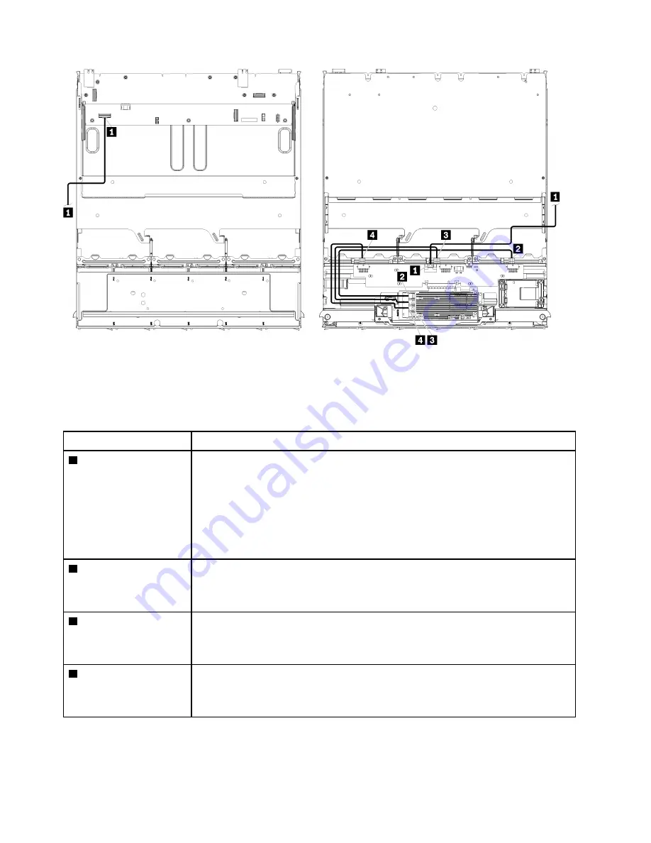
In this illustration, the image on the left shows the tray right-side up and the image on the right shows
the tray upside down.
Figure 19. Cable routing, SAS drive cables (upper tray with storage-board assembly)
Table 41. Cable routing, SAS drive cables (upper tray)
Cable
Routing
1
PCIe SAS interface
•
From:
– Lower system board in upper compute tray, “PCIe/NVMe” connector (see
“System-board connectors” on page 283)
– Storage-board assembly in upper tray, “PCIe” connector (see “Storage-board-
assembly connectors” on page 284)
•
To:
Storage interposer, “PCIe” connector (see “Storage interposer connectors” on
2
RAID interface for drive
backplane 4
•
From:
RAID card, “C3” connector (see “RAID card connectors” on page 290)
•
To:
Drive backplane, connector “SAS” (see “Drive backplane connectors” on page
3
RAID interface for drive
backplane 5
•
From:
RAID card, “C2” connector (see “RAID card connectors” on page 290)
•
To:
Drive backplane, connector “SAS” (see “Drive backplane connectors” on page
4
RAID interface for drive
backplane 6
•
From:
RAID card, “C1” connector (see “RAID card connectors” on page 290)
•
To:
Drive backplane, connector “SAS” (see “Drive backplane connectors” on page
NVMe drive cables (upper tray)
Common drive cables are used by only NVMe drives.
48
ThinkSystem SR950 Setup Guide
Содержание ThinkSystem SR950
Страница 1: ...ThinkSystem SR950 Setup Guide Machine Types 7X12 7X11 and 7X13 ...
Страница 55: ...Figure 22 Server components Chapter 2 Server components 51 ...
Страница 276: ...272 ThinkSystem SR950 Setup Guide ...
Страница 282: ...278 ThinkSystem SR950 Setup Guide ...
Страница 286: ...282 ThinkSystem SR950 Setup Guide ...
Страница 389: ......
Страница 390: ......