
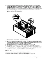


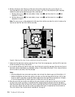


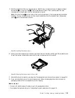


9. Insert the tab
1
on the cover presence switch frame into the corresponding hole in the chassis until
the frame is securely seated. Ensure that the screw hole in the cover presence switch frame is aligned
with the corresponding screw hole in the chassis. Then install the screw to secure the cover presence
switch assembly to the chassis.
Figure 81. Installing the cover presence switch assembly
10. Connect the cable of the new cover presence switch to the system board. See “System board
components” on page 37.
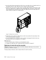
What to do next:
• To work with another piece of hardware, go to the appropriate section.
• To complete the replacement, go to “Completing the parts replacement” on page 141.
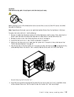
Replacing the front panel board assembly
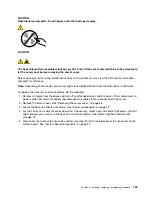
Attention:
Do not open your server or attempt any repair before reading and understanding “Safety information”
on page iii and “Guidelines” on page 63.
This topic provides instructions on how to replace the front panel board assembly.
Before you begin, print all the related instructions or ensure that you can view the PDF version on another
computer for reference.
Notes:
• Depending on the model, your server might look slightly different from the illustrations in this topic.
126
ThinkServer TS440 User Guide
Содержание ThinkServer TS440
Страница 1: ...ThinkServer TS440 User Guide Machine Types 70AL 70AM 70AN and 70AQ ...
Страница 16: ...4 ThinkServer TS440 User Guide ...
Страница 18: ...6 ThinkServer TS440 User Guide ...
Страница 56: ...44 ThinkServer TS440 User Guide ...
Страница 74: ...62 ThinkServer TS440 User Guide ...
Страница 166: ...154 ThinkServer TS440 User Guide ...
Страница 176: ...164 ThinkServer TS440 User Guide ...
Страница 181: ......
Страница 182: ......


