background image

• To complete the installation, go to “Completing the parts replacement” on page 135.

Removing a memory module

Attention:

Do not open your storage product or attempt any repair before reading and understanding “Safety

information” on page iii and “Guidelines” on page 49.

Before you begin, print all the related instructions or ensure that you can view the PDF version on another
computer for reference.

Note:

Ensure that you consider and follow the memory module installation rules when performing the

operation. See “Memory module installation rules” on page 61.

To remove a memory module, do the following:

1. Remove all media from the drives and turn off all attached devices and the storage product. Then,

disconnect all power cords from electrical outlets and disconnect all cables that are connected to
the storage product.

2. Prepare your storage product. See “Removing or extending the storage product from the rack cabinet”

on page 51.

3. Remove the storage product cover. See “Removing the cover” on page 51.

4. Remove the cooling shroud. See “Removing and reinstalling the cooling shroud” on page 54.

5. Locate the memory slots on the system board and read the memory module installation rules. See

“Memory module installation rules” on page 61.

6. Disconnect any cables that might impede your access to the memory slots.

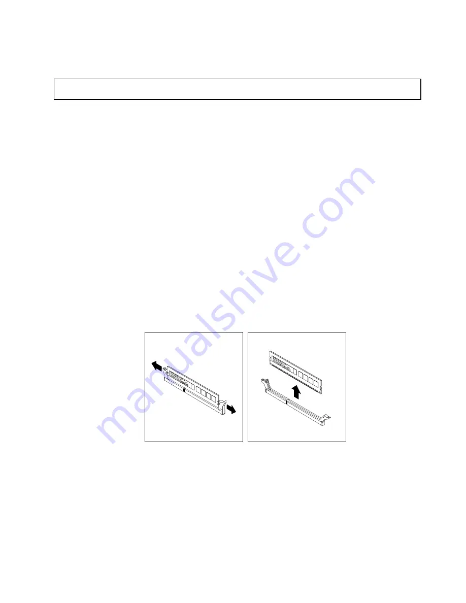
7. Locate the memory module that you want to remove and open the retaining clips on both ends of the

memory slot. Then, grasp the memory module by its edges and carefully pull it straight up to remove it
from the memory slot.

Figure 33. Removing a memory module

8. If you are instructed to return the old memory module, follow all packaging instructions and use any

packaging materials that are supplied to you for shipping.

What to do next:

• To work with another piece of hardware, go to the appropriate section.

• To complete the removal procedure, go to “Completing the parts replacement” on page 135.

Chapter 6

.

Replacing hardware

67

Содержание Storage N4610

Страница 1: ...Lenovo Storage N4610 User Guide and Hardware Maintenance Manual Machine Types 70G0 and 70G1 ...

Страница 2: ...ur product Safety information on page iii Appendix A Notices on page 149 First Edition February 2015 Copyright Lenovo 2015 LIMITED AND RESTRICTED RIGHTS NOTICE If data or software is delivered pursuant a General Services Administration GSA contract use reproduction or disclosure is subject to restrictions set forth in Contract No GS 35F 05925 ...

Страница 3: ...d time 40 Using passwords 40 Selecting a startup device 41 Setting an Ethernet connector for system management 42 Exiting the Setup Utility program 42 Updating or recovering the BIOS 42 Configuring RAID 44 About RAID 44 Configuring RAID using the Lenovo ThinkServer Deployment Manager program 46 Configuring the advanced SATA or SAS hardware RAID 46 Updating the firmware 46 Chapter 6 Replacing hardw...

Страница 4: ... program problems 140 Storage drive problems 140 Memory module problems 141 Keyboard mouse and USB device problems 142 Chapter 8 Getting information help and service 145 Information resources 145 Using the documentation 145 Lenovo Storage Web site 145 Lenovo Support Web site 145 Help and service 146 Before you call 146 Calling for service 146 Using other services 147 Purchasing additional services...

Страница 5: ...teen käyttöä Avant d utiliser le produit veillez à bien lire et comprendre les instructions de sécurité multilingues figurant sur le DVD de documentation fourni avec le produit Πριν χρησιμοποιήσετε το προϊόν βεβαιωθείτε ότι έχετε διαβάσει και κατανοήσει τις οδηγίες ασφάλειας οι οποίες είναι διαθέσιμες σε διάφορες γλώσσες στο DVD τεκμηρίωσης που συνοδεύει το προϊόν Vor Verwendung des Produkts sollt...

Страница 6: ... produktom Preden začnete uporabljati izdelek je pomembno da preberete in razumete večjezična varnostna navodila na DVD ju z dokumentacijo ki ste ga prejeli skupaj z izdelkom Antes de utilizar el producto asegúrese de leer y comprender las instrucciones de seguridad multilingües del DVD de documentación que se proporciona con el producto Var noga med att läsa säkerhetsinstruktionerna på dokumentat...

Страница 7: ...ess instructed otherwise in the installation and configuration procedures Connect and disconnect cables as described in the following table when installing moving or opening covers on this product or attached devices To connect To disconnect 1 Turn everything OFF 2 First attach all cables to devices 3 Attach signal cables to connectors 4 Attach power cords to outlets 5 Turn devices ON 1 Turn every...

Страница 8: ...s 3B laser diode Note the following Laser radiation when open Do not stare into the beam do not view directly with optical instruments and avoid direct exposure to the beam Statement 4 18 kg 39 7 lb 32 kg 70 5 lb 55 kg 121 2 lb 32 kg 70 5 lb 55 kg 121 2 lb 100 kg 220 5 lb CAUTION Use safe practices when lifting Statement 5 CAUTION The power control button on the device and the power switch on the ...

Страница 9: ...oors will not support the weight of the device Statement 8 CAUTION Never remove the cover on a power supply or any part that has the following label attached Hazardous voltage current and energy levels are present inside any component that has this label attached There are no serviceable parts inside these components If you suspect a problem with one of these parts contact a service technician Sta...

Страница 10: ...ed on the rails Statement 14 CAUTION Some accessory or option board outputs exceed Class 2 or limited power source limits You must install the appropriate interconnecting cabling in accordance with your local electrical code requirements Statement 15 CAUTION The power control button on the device may put the device in standby mode instead of turning off the device In addition the device might have...

Страница 11: ...ements Use 1 3 mm2 or 16 American Wire Gauge AWG copper conductor only not exceeding 3 meters in length Torque the wiring terminal screws to 1 4 newton meters or 12 inch pounds Provide a readily available approved and rated disconnect device in the field wiring Statement 17 CAUTION This product contains a Class 1M laser Do not view directly with optical instruments Statement 18 CAUTION Do not plac...

Страница 12: ... you can continue without first correcting the problem Consider these conditions and the safety hazards they present Electrical hazards especially primary power primary voltage on the frame can cause serious or fatal electrical shock Explosive hazards such as a damaged Cathode Ray Tube CRT monitor or a bulging capacitor Mechanical hazards such as loose or missing hardware To determine whether ther...

Страница 13: ...r worn frayed or pinched cables 9 Check that the power supply cover fasteners screws or rivets have not been removed or tampered with Grounding requirements Electrical grounding of the storage is required for operator safety and correct system function Proper grounding of the electrical outlet can be verified by a certified electrician Copyright Lenovo 2015 xi ...

Страница 14: ...xii Lenovo Storage N4610 User Guide and Hardware Maintenance Manual ...

Страница 15: ... latest LLW also is available in more than 30 languages at http www lenovo com warranty llw_02 If you cannot obtain the LLW through the documentation DVD or Lenovo Web site contact your local Lenovo office or reseller to obtain a printed version of the LLW free of charge For warranty service consult the worldwide Lenovo Support telephone list Telephone numbers are subject to change without notice ...

Страница 16: ...oduct with Lenovo you will receive quicker service when you call Lenovo for help In addition some locations offer extended privileges and services to registered users Documentation This topic provides a general description of each document for your storage product and instructions on how to obtain all the documents Printed documents The following documents are printed out and included in your stor...

Страница 17: ... Web site at http www lenovo com support The following documents are on the documentation DVD that comes with your storage product Safety Warranty and Support Information This is a multilingual document that includes all the safety statements for your product in more than 30 languages Be sure to read and understand all the safety statements before using the product This document also includes the ...

Страница 18: ...4 Lenovo Storage N4610 User Guide and Hardware Maintenance Manual ...

Страница 19: ... storage product See the Rack Installation Instructions that comes with the storage product 4 Connect the Ethernet cables and power cords to the storage product See Rear view of the storage product on page 18 to locate the connectors 5 Turn on the storage product to verify operation See Turning on the storage product on page 35 6 Review the Basic Input Output System BIOS settings and customize as ...

Страница 20: ...6 Lenovo Storage N4610 User Guide and Hardware Maintenance Manual ...

Страница 21: ...el some features might vary or unavailable For information about your specific model use the Setup Utility program See Viewing information in the Setup Utility program on page 37 You also can refer to the Product Specifications Reference document for Lenovo Storage products at http www lenovo com psref Microprocessor One or two Intel Xeon microprocessors internal cache size varies by model For a l...

Страница 22: ... Drive bay size Drive bay quantity Drive type 3 5 inch 12 Hot swap SATA or SAS 3 5 inch hard disk drive or 2 5 inch solid state drive Note You can install a 2 5 inch solid state drive into a 3 5 inch drive bay For more information see Installing a 2 5 inch solid state drive into a 3 5 inch drive bay on page 111 In the rear Drive bay size Drive bay quantity Drive type 2 5 inch 2 Hot swap SATA Hard ...

Страница 23: ...connector on the rear panel with 10 megabits per second Mbps 100 Mbps or 1000 Mbps network connectivity The Ethernet connector is for system management You can install an Ethernet card or an AnyFabric adapter to enable more Ethernet connectors However you must install a device driver to enable the operating system to recognize the Ethernet connectors The device drivers are available for download a...

Страница 24: ...tions including turning on or off the storage product restarting the storage product and so on This part of storage product management is independent of the operating system and is called out of band management The system board platform management subsystem consists of the integrated TSM communication buses sensors the BIOS and storage product management firmware It is responsible for error report...

Страница 25: ...nced system management features The advanced system management features are only available when the TSM detects the presence of a TSM Premium module The TSM Premium module is a remote management module You can purchase a TSM Premium module from Lenovo and install it on the system board to activate the advanced system management features For more information about advanced system management refer t...

Страница 26: ...a dependent variable A2 The temperature value decreases by 1 C 33 8 F with every 300 m 984 ft of altitude increase A3 The temperature value decreases by 1 C 33 8 F with every 175 m 574 ft of altitude increase A4 The temperature value decreases by 1 C 33 8 F with every 125 m 410 ft of altitude increase Your storage product complies with ASHRAE class A2 specifications Depending on the hardware confi...

Страница 27: ...terface Deployment Manager has the following features Easy to use language selectable interface Integrated help system Automatic hardware detection Selectable partition size and file system type Ability to install the operating system and device drivers in an unattended mode to save time Ability to create a reusable response file that can be used with similarly configured Lenovo storage products t...

Страница 28: ... detailed information about using the Lenovo ThinkServer System Manager program refer to the help system of the program Lenovo ThinkServer System Manager Premium Lenovo ThinkServer System Manager Premium provides you a solution that enables you to receive all the benefits and features provided by the Lenovo ThinkServer System Manager program It also enables you to control the storage product remot...

Страница 29: ...u can use the rack handles to help you slide the storage product out of the rack cabinet You also can use the rack handles and screws to secure the storage product in the rack cabinet so that the storage product cannot slide out especially in vibration prone areas For more information refer to the Rack Installation Instructions that comes with your storage product 2 Front panel For information abo...

Страница 30: ...connectors and LEDs on the front panel of the storage product To locate the front panel see Front view of the storage product on page 15 1 3 2 4 Figure 3 Front panel 1 Network status LED 2 System health LED 3 Power button with power status LED 4 System ID button with ID LED 1 Network status LED The network status LED on the front panel helps you identify the network connectivity and activity Statu...

Страница 31: ...Check the BMC for detailed information The power cord has been disconnected from one power supply or a redundant power supply has been removed 1 Ensure that the power supplies are installed securely in the storage product 2 Ensure that the power cords are connected securely to the power supplies 3 Install a new power supply to replace the removed one On Amber The THERMTRIP signal is asserted becau...

Страница 32: ...models 2 Power supply 1 3 PCIe slot 8 4 PCIe slot 7 5 PCIe slot 5 on riser card assembly 2 6 PCIe slot 6 on riser card assembly 2 7 PCIe slot 4 8 PCIe slot 1 on riser card assembly 1 9 PCIe slot 2 on riser card assembly 1 10 PCIe slot 3 on riser card assembly 1 11 AnyFabric slot 12 DisplayPort connector 13 Serial connector 14 USB 3 0 connectors 2 15 2 5 inch drive bays 2 16 Ethernet connector for ...

Страница 33: ...able link width Supported card length and height 8 PCIe slot 1 x16 x8 x4 x2 x1 Half length full height card 9 PCIe slot 2 x16 x8 x4 x2 x1 Half length full height card 10 PCIe slot 3 x16 x8 x4 x2 x1 Half length full height card 11 AnyFabric slot Used to install an AnyFabric adapter also called mezzanine adapter 12 DisplayPort connector Used to attach a high performance monitor a direct drive monito...

Страница 34: ...When you press the ID button on the front panel the ID LEDs on both the front and rear of the storage product are lit to help you locate the storage product among other storage products You also can turn on the ID LEDs using a remote management program for storage product presence detection Status Color Description On Blue The storage product is identified Off None The ID LED is not in use or the ...

Страница 35: ...er 6 Front backplane 7 System fan cage 8 System fan 9 System board 10 CPU1 DIMMs vary by model 11 Heat sink 12 Coin cell battery 13 AnyFabric adapter available on some models 14 Cooling shroud 15 ThinkServer RAID Super Capacitor Module available on some models 16 Riser card assembly 17 PCIe card available on some models 18 Intrusion switch available on some models 19 Rear backplane cage assembly 2...

Страница 36: ...ion information For a complete listing of FRU information such as FRU part numbers and supported storage product models go to http www lenovo com serviceparts lookup Notes Before servicing a Lenovo product ensure that you read and understand Safety information on page iii Use only parts provided by Lenovo Available on some models FRU description Self service CRU Optional service CRU AnyFabric adap...

Страница 37: ...duct also supports the Host Bus Adapter HBA You can use a Host Bus Adapter to connect your storage product to external storage devices such as a storage array You can purchase a supported AnyRAID adapter and Host Bus Adapter from Lenovo and install it into the storage product For a list of storage product options go to http shop lenovo com us en servers network storage Note The option kit is desig...

Страница 38: ...ver RAID Super Capacitor Module connector Used to connect to the ThinkServer RAID Super Capacitor Module See Storage product components on page 20 3 PCIE 0 connector 4 PCIE 1 connector Used to connect to the AnyRAID connector 0 1 on the system board See System board components on page 26 Hot swap drive backplane Your storage product comes with the following drive bay and backplane configurations I...

Страница 39: ...e front backplane 0 1 2 3 4 5 6 7 8 9 10 11 Figure 8 Front view of the front backplane 12 13 14 15 Figure 9 Rear view of the front backplane 0 11 Slot 0 slot 11 Used to connect 3 5 inch drives 12 10 pin power connector 0 13 10 pin power connector 1 Used to connect to the 10 pin backplane power connectors on the power distribution board to provide power to the backplane 14 AnyRAID adapter slot 0 15...

Страница 40: ...ector 0 6 Drive connector 1 Used to connect to the SATA connector on the Lenovo ThinkServer RAID 720ix AnyRAID Adapter 3 4 pin power connector Used to connect to the rear backplane power connector on the system board 5 Rear backplane signal connector Used to connect to the rear backplane signal connector on the system board System board components The following illustration shows the component loc...

Страница 41: ...essor 2 memory slots 6 18 System fan 5 connector 19 Microprocessor 2 socket 20 System fan 4 connector 21 Microprocessor 2 memory slots 6 22 System fan 3 connector 23 Microprocessor 1 memory slots 6 24 System fan 2 connector 25 Microprocessor 1 socket 26 System fan 1 connector 27 Microprocessor 1 memory slots 6 1 AnyRAID connector 0 1 Used to connect to the PCIe connectors on the AnyRAID adapter 2 ...

Страница 42: ... for up to two 2 5 inch drives 9 Riser card assembly 2 slot Used to install the riser card assembly 2 12 Rear backplane power connector Used to connect to the 4 pin power connector on the rear backplane 13 Front backplane power connector Used to connect to the 10 pin power connector on the front backplane 14 Intrusion switch connector Used to connect to an intrusion switch 15 Power distribution bo...

Страница 43: ...he system board first Do not open your storage product or attempt any repair before reading and understanding Safety information on page iii and Guidelines on page 49 1 BIOS default settings jumper Used to turn the BIOS settings into the factory default settings To turn the BIOS settings into the factory default settings do the following 1 Remove all external media from the drives and turn off all...

Страница 44: ...t are connected to the storage product 2 Prepare your storage product See Removing or extending the storage product from the rack cabinet on page 51 3 Remove the storage product cover See Removing the cover on page 51 4 Locate the clear password jumper 2 on the system board Then remove any parts and disconnect any cables that might impede your access to the jumper Note Do not remove the memory mod...

Страница 45: ...ng illustration shows the system fan fault LEDs 1 on the system board 1 Figure 14 System fan fault LEDs You can view the system fan fault LEDs 1 from the top of the system fans When a system fan fault LED is lit it indicates that the corresponding system fan is operating slowly or has failed To solve the problem reinstall or replace the system fan See Installing or replacing a system fan on page 5...

Страница 46: ...t but not in use Blinking green Off The drive is active and data is being transferred On green Blinking rapidly about four flashes per second amber The RAID controller is identifying the drive On green On amber The RAID array has failed and cannot be recovered You need to recreate a new array Blinking green Blinking slowly about one flash per second amber The drive is being rebuilt 32 Lenovo Stora...

Страница 47: ...ld redundancy active mode No action is needed Blinking green about two flashes each second The power supply is in cold redundancy sleep mode No action is needed 2 Output status LED On green The storage product is on and the power supply is working normally No action is needed Off The power supply is working normally No action is needed 3 Fault LED On amber The power supply has failed Replace the p...

Страница 48: ...34 Lenovo Storage N4610 User Guide and Hardware Maintenance Manual ...

Страница 49: ...not turn off the electrical current supplied to the device The device also might have more than one power cord To remove all electrical current from the device ensure that all power cords are disconnected from the power source The storage product can be turned off in one of the following ways Turn off the storage product from the operating system if your operating system supports this feature Afte...

Страница 50: ...est to turn on the storage product To remove all power from the storage product you must disconnect the storage product from the ac power source For information about your specific operating system refer to the related documentation or help system for the operating system 36 Lenovo Storage N4610 User Guide and Hardware Maintenance Manual ...

Страница 51: ...lists various items about the system configuration Select a desired item to view information or change settings When working with the Setup Utility program you must use the keyboard The keys used to perform various tasks are displayed on the right bottom pane of each screen You also can press the F1 key for general help about the keys For most items the corresponding help message is displayed on t...

Страница 52: ...settings on the Advanced Settings menu in the Setup Utility program The Advanced Settings menu contains various configuration submenus and items On each submenu press Enter to show selectable options and select a desired option by using the up and down arrow keys or type desired values from the keyboard Some items are displayed on the menu only if the storage product supports the corresponding fea...

Страница 53: ...nd refer to the instructions on the screen TSM Network Settings Set BMC management network configuration parameters User Account Settings Set BMC user account parameters Boot Manager menu The Boot Manager menu in the Setup Utility program lists all the bootable devices installed in your storage product and the listed items vary depending on your storage product configuration The Boot Sequence subm...

Страница 54: ...ng security If you decide to set a password read the following topics Setup Utility program password types The following types of passwords are available in the Setup Utility program Administrator password Setting an administrator password deters unauthorized users from changing configuration settings If you are responsible for maintaining the configuration settings of several computers you might ...

Страница 55: ...red Note For security reasons it is recommended that you always set a password for your storage product 5 Press F10 to save settings and exit the Setup Utility program If you have forgotten the password you can use the clear password jumper on the system board to erase the password See System board jumpers on page 29 Then set a new password for the storage product Selecting a startup device If you...

Страница 56: ...ce If you are on a nested submenu press Esc repeatedly until you reach the main interface Then you can do one of the following to exit the Setup Utility program If you want to save the new settings and exit the Setup Utility program press F10 or select Save Exit Save Changes and Reset Otherwise your changes will not be saved If you do not want to save the new settings select Save Exit Discard Chan...

Страница 57: ...date failure Note If the operating system of your storage product is installed under EFI mode reinstall the operating system after recovering the BIOS To recover from a BIOS update failure do one of the following Using the automatic recovery feature 1 Reconnect the storage product to an ac power source 2 After the system health LED turns off press the power button to turn on the storage product Th...

Страница 58: ...ncreased storage functions and reliability through redundancy This is achieved by combining multiple hard disk drives into a logical unit where data is distributed across the drives in one of several ways called RAID levels When a group of independent physical hard disk drives are set up to use RAID technology they are in a RAID array This array distributes data across multiple hard disk drives bu...

Страница 59: ...used to recover the data if one or two drives fail in the drive group RAID 6 requires a minimum number of three hard disk drives RAID 10 a combination of RAID 0 and RAID 1 RAID 10 consists of striped data across mirrored spans A RAID 10 drive group is a spanned drive group that creates a striped set from a series of mirrored drives RAID 10 allows a maximum of eight spans You must use an even numbe...

Страница 60: ...nterface Infrastructure HII configuration utility This utility enables you to configure RAID independently of the operating system To display the HII configuration utility interface start the storage product and press the F1 key as soon as you see the screen to enter the Setup Utility program Then select Boot Manager Adapters and UEFI Drivers MegaRAID Storage Manager program This program provides ...

Страница 61: ... and follow the instructions on the Web page to check for the latest level of firmware such as the BIOS updates and device drivers Use the Lenovo ThinkServer Deployment Manager program See Lenovo ThinkServer Deployment Manager on page 13 Chapter 5 Configuring the storage product 47 ...

Страница 62: ...48 Lenovo Storage N4610 User Guide and Hardware Maintenance Manual ...

Страница 63: ...to http www lenovo com drivers and follow the instructions on the Web page See Updating the firmware on page 46 for more information Before you install optional hardware devices ensure that the storage product is working correctly If the storage product is not working correctly see Chapter 7 Troubleshooting and diagnostics on page 139 to do basic troubleshooting If the problem cannot be solved see...

Страница 64: ...t of the storage product for at least two seconds This reduces static electricity from the package and your body Remove the new part from the static protective package and directly install it in the storage product without placing it on any other surface If it is hard for you to do this in your specific situation place the static protective package of the new part on a smooth level surface and the...

Страница 65: ...it Avoid dropping any metallic objects into the storage product such as paper clips hairpins and screws Removing or extending the storage product from the rack cabinet If the storage product is installed in a rack cabinet remove or extend the storage product from the rack cabinet before installing or replacing hardware Depending on the rail type do one of the following If the storage product is in...

Страница 66: ...isengaged from the chassis Then lift the storage product cover off the chassis and set it aside Note It is recommended that you wait several minutes to let the storage product cool before removing the storage product cover Figure 19 Removing the storage product cover Attention For proper cooling and airflow install the cover before turning on the storage product Operating the storage product with ...

Страница 67: ...upied When you install an internal drive or a PCI card save the EMI shield or dummy tray from the drive bay or save the PCI card slot bracket in the event that you later remove the device Attention An unoccupied drive bay or PCIe card slot without a cover shield dummy tray filler or any other protection might impact the EMI integrity and cooling of the storage product which might result in overhea...

Страница 68: ...rage product Before you begin print all the related instructions or ensure that you can view the PDF version on another computer for reference To remove and reinstall the cooling shroud do the following 1 Remove all media from the drives and turn off all attached devices and the storage product Then disconnect all power cords from electrical outlets and disconnect all cables that are connected to ...

Страница 69: ...5 Insert your fingers into the holes 1 in the cooling shroud and lift it out of the storage product 1 Figure 22 Removing the cooling shroud Chapter 6 Replacing hardware 55 ...

Страница 70: ...both sides of the chassis Figure 23 Installing the cooling shroud 7 Go to Completing the parts replacement on page 135 Attention For proper cooling and airflow reinstall the cooling shroud before turning on the storage product Operating the storage product with the cooling shroud removed might damage storage product components Installing or replacing a system fan Attention Do not open your storage...

Страница 71: ... following 1 Remove the storage product cover Note The system fans are hot swap and you can replace a failing system fan without turning off the storage product 2 Do one of the following If you are installing a system fan grasp the top of the dummy fan with your index finger and thumb and then lift the dummy fan out of the storage product Figure 24 Removing the dummy fan If you are replacing a sys...

Страница 72: ... that the system fan connector on the bottom of the new system fan is facing the rear of the chassis Then press the new system fan straight down until it is seated into place Figure 26 Installing the system fan 5 If you are instructed to return the old system fan follow all packaging instructions and use any packaging materials that are supplied to you for shipping What to do next To work with ano...

Страница 73: ...do the following 1 Remove all media from the drives and turn off all attached devices and the storage product Then disconnect all power cords from electrical outlets and disconnect all cables that are connected to the storage product 2 Prepare your storage product See Removing or extending the storage product from the rack cabinet on page 51 3 Remove the storage product cover See Removing the cove...

Страница 74: ...m board Figure 28 Installing the system fan cage 6 Pivot the tabs of the system fan cage to the front of the storage product to secure the system fan cage Figure 29 Securing the system fan cage What to do next To work with another piece of hardware go to the appropriate section To complete the replacement go to Completing the parts replacement on page 135 Installing or removing a memory module Thi...

Страница 75: ...sors installed and one 32 GB LRDIMM installed in each of the 24 memory slots For more information about the memory modules in your specific storage product model use the Setup Utility program See Viewing information in the Setup Utility program on page 37 For a list of storage product options go to http shop lenovo com us en servers network storage Before installing a memory module ensure that you...

Страница 76: ...ates the memory slots into which the memory modules should be installed in different situations Table 2 Memory module installation rules for storage products with one microprocessor CPU1 DIMM A1 A2 A3 B1 B2 B3 C1 C2 C3 D1 D2 D3 1 DIMM X 2 DIMMs X X 4 DIMMs X X X X 8 DIMMs X X X X X X X X 12 DIMMs X X X X X X X X X X X X The following table provides information about the memory module installation ...

Страница 77: ...ssor CPU1 installed Table 4 Memory module installation order in independent mode for storage products with one microprocessor CPU1 DIMM A1 A2 A3 B1 B2 B3 C1 C2 C3 D1 D2 D3 DIMM installation order 1 5 9 2 6 10 3 7 11 4 8 12 The following table explains the memory module installation order for storage products that have two microprocessors CPU1 and CPU2 installed Table 5 Memory module installation o...

Страница 78: ...e type with the same capacity frequency voltage and number of ranks Your storage product supports rank sparing mode In rank sparing mode one rank of a memory module works as the spare rank for the other ranks on the same channel The spare rank is not available as system memory To enable rank sparing mode ensure that At least three ranks are available in one channel At least two memory modules are ...

Страница 79: ...IMM installation order 1 1 9 3 3 11 5 5 13 7 7 15 2 2 10 4 4 12 6 6 14 8 8 16 Installing a memory module Attention Do not open your storage product or attempt any repair before reading and understanding Safety information on page iii and Guidelines on page 49 Before you begin print all the related instructions or ensure that you can view the PDF version on another computer for reference Notes Ensu...

Страница 80: ...dges 9 Position the new memory module over the memory slot Ensure that the notch 1 on the new memory module is aligned with the key 2 in the memory slot Then press the new memory module straight down into the memory slot until the retaining clips close and the new memory module snaps into position Note If there is a gap between the memory module and the retaining clips the memory module has not be...

Страница 81: ...r extending the storage product from the rack cabinet on page 51 3 Remove the storage product cover See Removing the cover on page 51 4 Remove the cooling shroud See Removing and reinstalling the cooling shroud on page 54 5 Locate the memory slots on the system board and read the memory module installation rules See Memory module installation rules on page 61 6 Disconnect any cables that might imp...

Страница 82: ...s from electrical outlets and disconnect all cables that are connected to the storage product 2 Prepare your storage product See Removing or extending the storage product from the rack cabinet on page 51 3 Remove the storage product cover See Removing the cover on page 51 4 Loosen the screw that secures the riser card assembly Then grasp the assembly by its edges and carefully lift it straight up ...

Страница 83: ...ard 8 Touch the static protective package that contains the new riser card to any unpainted surface on the outside of the storage product Then remove the new riser card from the package 9 Align the screw holes in the new riser card with the corresponding ones in the bracket Figure 36 Installing the riser card Chapter 6 Replacing hardware 69 ...

Страница 84: ...PCIe cards on the new riser card See Installing a PCIe card on the riser card assembly on page 75 12 Refer to your note to reconnect any cables to the PCIe cards on the new riser card You also can refer to Connecting cables on page 33 for information about cable connections 70 Lenovo Storage N4610 User Guide and Hardware Maintenance Manual ...

Страница 85: ... the corresponding rail guides in the rear of the chassis Then carefully press the riser card assembly straight down into the chassis until it is fully seated Note Carefully fit the installed PCIe cards into the chassis and properly route any cables from the cards Figure 38 Installing the riser card assembly Chapter 6 Replacing hardware 71 ...

Страница 86: ...d types of PCI Express cards This topic provides instructions on how to install or remove a PCI Express PCIe card such as an Ethernet card a Host Bus Adapter and any other supported PCIe cards This topic contains the following information Installing a PCIe card on page 72 Removing a PCIe card on page 80 Note The PCIe card is extremely sensitive to ESD Ensure that you read and understand Handling s...

Страница 87: ...meet the following requirements The length of the PCIe card to be installed is either of the following 176 4 mm 6 94 inches 185 mm 7 28 inches 220 mm 8 66 inches The riser card bracket supports half length PCIe cards by default To adjust the card retaining bracket do the following 1 Remove the three screws that secure the card retaining bracket Then move the card retaining bracket to the direction...

Страница 88: ...the card retaining bracket for 176 4 mm 6 94 inches PCIe cards If the length of the PCIe card is between 185 mm 7 28 inches and 220 mm 8 66 inches move the card retaining bracket to an appropriate position Then install the three screws to secure the card retaining bracket Figure 42 Securing the card retaining bracket for PCIe cards between 185 mm 7 28 inches and 220 mm 8 66 inches 74 Lenovo Storag...

Страница 89: ... do the following 1 Remove all media from the drives and turn off all attached devices and the storage product Then disconnect all power cords from electrical outlets and disconnect all cables that are connected to the storage product 2 Prepare your storage product See Removing or extending the storage product from the rack cabinet on page 51 3 Remove the storage product cover See Removing the cov...

Страница 90: ...Then carefully press the PCIe card straight into the slot until it is securely seated Ensure that the PCIe card bracket is secured by the riser card bracket Figure 44 Installing the PCIe card 9 Pivot the card latch to the closed position to secure the PCIe card in position Figure 45 Pivoting the card latch to the closed position 10 Depending on the type of the PCIe card you might need to connect a...

Страница 91: ...ith the PCIe card and follow those instructions in addition to the instructions in this topic To install a PCIe card on the system board do the following 1 Remove all media from the drives and turn off all attached devices and the storage product Then disconnect all power cords from electrical outlets and disconnect all cables that are connected to the storage product 2 Prepare your storage produc...

Страница 92: ...ly handle the PCIe card by its edges 7 If you want to install the PCIe card into the slot for a low profile card you might need to replace the full height bracket with the low profile bracket To replace the bracket do the following Note Depending on the specific type the PCIe card and its bracket might look different from the following illustrations a Carefully remove the screws that secure the PC...

Страница 93: ...he screws to secure the bracket to the PCIe card Figure 49 Installing the low profile bracket 8 Position the PCIe card near the PCIe slot Then carefully press the PCIe card straight into the slot until it is securely seated and its bracket also is secured by the chassis Figure 50 Installing the PCIe card Chapter 6 Replacing hardware 79 ...

Страница 94: ...ing a PCIe card from the riser card assembly Attention Do not open your storage product or attempt any repair before reading and understanding Safety information on page iii and Guidelines on page 49 Before you begin print all the related instructions or ensure that you can view the PDF version on another computer for reference Notes Depending on the specific type the PCIe card might look differen...

Страница 95: ...extending the storage product from the rack cabinet on page 51 3 Remove the storage product cover See Removing the cover on page 51 4 Remove the riser card assembly and lay it upside down on a flat clean and static protective surface See Replacing the riser card on page 68 5 Locate the PCIe card you want to remove Then press the tab to pivot the card latch to the open position Figure 52 Pivoting t...

Страница 96: ... the removal procedure go to Completing the parts replacement on page 135 Removing a PCIe card from the system board Attention Do not open your storage product or attempt any repair before reading and understanding Safety information on page iii and Guidelines on page 49 Before you begin print all the related instructions or ensure that you can view the PDF version on another computer for referenc...

Страница 97: ... that are supplied to you for shipping What to do next To work with another piece of hardware go to the appropriate section To complete the removal procedure go to Completing the parts replacement on page 135 Replacing the AnyRAID adapter Attention Do not open your storage product or attempt any repair before reading and understanding Safety information on page iii and Guidelines on page 49 Before...

Страница 98: ...omponents on page 20 5 Loosen the two screws and grasp the AnyRAID adapter by its edges and carefully pull it out Note The AnyRAID adapter might fit tightly into the slots If necessary alternate moving each side of the AnyRAID adapter a small and equal amount until it is removed from the slots Figure 55 Removing the AnyRAID adapter 6 Touch the static protective package that contains the new AnyRAI...

Страница 99: ...the screws 9 If you are instructed to return the old AnyRAID adapter follow all packaging instructions and use any packaging materials that are supplied to you for shipping What to do next To work with another piece of hardware go to the appropriate section To complete the replacement go to Completing the parts replacement on page 135 Installing or removing the flash module This topic applies only...

Страница 100: ...from the drives and turn off all attached devices and the storage product Then disconnect all power cords from electrical outlets and disconnect all cables that are connected to the storage product 2 Prepare your storage product See Removing or extending the storage product from the rack cabinet on page 51 3 Remove the storage product cover See Removing the cover on page 51 4 Locate the AnyRAID ad...

Страница 101: ...orage product 2 Prepare your storage product See Removing or extending the storage product from the rack cabinet on page 51 3 Remove the storage product cover See Removing the cover on page 51 4 Locate the AnyRAID adapter See Storage product components on page 20 5 Remove any parts and disconnect any cables that might impede your operation 6 Press the two release tabs 1 and lift the flash module s...

Страница 102: ...r ensure that you can view the PDF version on another computer for reference Notes Use any documentation that comes with the TSM Premium module and follow those instructions in addition to the instructions in this topic Depending on the model your storage product might look slightly different from the illustration in this topic To install the TSM Premium module do the following 1 Remove all media ...

Страница 103: ...lated instructions or ensure that you can view the PDF version on another computer for reference Notes If you remove the TSM Premium module the iKVM function for storage product remote management will be unavailable Use any documentation that comes with the TSM Premium module and follow those instructions in addition to the instructions in this topic Depending on the model your storage product mig...

Страница 104: ... http shop lenovo com us en servers network storage Installing the AnyFabric adapter Attention Do not open your storage product or attempt any repair before reading and understanding Safety information on page iii and Guidelines on page 49 Before you begin print all the related instructions or ensure that you can view the PDF version on another computer for reference Notes Use any documentation th...

Страница 105: ...Fabric adapter and need the shield to cover the bay Figure 62 Removing the protective shield for the AnyFabric adapter bay 7 Touch the static protective package that contains the AnyFabric adapter to any unpainted surface on the outside of the storage product Then take the AnyFabric adapter out of the package Note Carefully handle the AnyFabric adapter by its edges 8 Slide the AnyFabric adapter in...

Страница 106: ...power cords from electrical outlets and disconnect all cables that are connected to the storage product 2 Prepare your storage product See Removing or extending the storage product from the rack cabinet on page 51 3 Remove the storage product cover See Removing the cover on page 51 4 Remove the riser card assembly 1 See Replacing the riser card on page 68 5 Locate the AnyFabric adapter See Storage...

Страница 107: ...following label attached Hazardous voltage current and energy levels are present inside any component that has this label attached There are no serviceable parts inside these components If you suspect a problem with one of these parts contact a service technician Before you begin print all the related instructions or ensure that you can view the PDF version on another computer for reference Notes ...

Страница 108: ...the rear of your storage product and disconnect the power cord from the failing power supply Note On each power supply there are three status LEDs near the power cord connector For information about the status LEDs see Power supply status LEDs on page 33 b Press the release tab 1 in the direction as shown and carefully pull the handle 2 at the same time to slide the failing power supply out of the...

Страница 109: ... your storage product or attempt any repair before reading and understanding Safety information on page iii and Guidelines on page 49 CAUTION The heat sink might be very hot Turn off the storage product and wait several minutes to let the storage product cool before removing the storage product cover Before you begin print all the related instructions or ensure that you can view the PDF version on...

Страница 110: ...ntly twist the heat sink to free it from the microprocessor and then lift the heat sink off the system board c Lay aside the old heat sink Notes Use a cleaning pad to wipe the thermal grease from the top of the microprocessor before installing the new heat sink Dispose of the cleaning pad after all of the thermal grease is removed from the microprocessor When handling the heat sink do not touch th...

Страница 111: ...croprocessor This topic contains the following information Installing the second microprocessor on page 97 Replacing the microprocessor on page 101 Installing the second microprocessor Attention Do not open your storage product or attempt any repair before reading and understanding Safety information on page iii and Guidelines on page 49 Depending on the model your storage product might come with ...

Страница 112: ...trical outlets and disconnect all cables that are connected to the storage product 2 Prepare your storage product See Removing or extending the storage product from the rack cabinet on page 51 3 Remove the storage product cover See Removing the cover on page 51 4 Remove the cooling shroud See Removing and reinstalling the cooling shroud on page 54 5 Locate the microprocessor socket 2 on the system...

Страница 113: ...ocessor retainer 8 Touch the static protective package that contains the new microprocessor to any unpainted surface on the outside of the storage product Then remove the new microprocessor from the package 9 Remove the new microprocessor from the protective cover that protects the gold contacts on the bottom of the new microprocessor Do not touch the pins on the microprocessor socket and the gold...

Страница 114: ...en this indicator faces the beveled corner 4 of the microprocessor socket Figure 73 Installing the microprocessor 11 Remove the plastic microprocessor socket cover Store the microprocessor socket cover in the event that you later remove the microprocessor and need the socket cover to protect the pins on the socket Note Do not remove the socket cover until you install a microprocessor into the sock...

Страница 115: ...ion kit See Installing or replacing a heat sink on page 95 What to do next To work with another piece of hardware go to the appropriate section To complete the installation go to Completing the parts replacement on page 135 Replacing the microprocessor Attention Do not open your storage product or attempt any repair before reading and understanding Safety information on page iii and Guidelines on ...

Страница 116: ...ct 2 Prepare your storage product See Removing or extending the storage product from the rack cabinet on page 51 3 Remove the storage product cover See Removing the cover on page 51 4 Remove the cooling shroud See Removing and reinstalling the cooling shroud on page 54 5 Remove the heat sink See Installing or replacing a heat sink on page 95 6 Locate the microprocessor socket Open the small handle...

Страница 117: ...t Place the old microprocessor on a static protective surface Notes Do not touch the gold contacts on the bottom of the microprocessor Do not drop anything onto the microprocessor socket while it is exposed The socket pins must be kept as clean as possible Figure 78 Removing the microprocessor 9 Touch the static protective package that contains the new microprocessor to any unpainted surface on th...

Страница 118: ... microprocessor by its edges and align the notches 1 on it with the tabs 2 in the microprocessor socket Then carefully lower the new microprocessor straight down into the microprocessor socket Note The small triangle 3 on one corner of the new microprocessor is the microprocessor orientation indicator The new microprocessor is in the correct orientation when this indicator faces the beveled corner...

Страница 119: ...ease is removed 14 Use one of the following methods to apply appropriate amount of thermal grease to the top of the newly installed microprocessor in the shape of a cross or a circle as shown Using too much or too little thermal grease can cause a thermal problem due to imperfect contact with the components Notes Do not touch the thermal grease Keep the thermal grease off the system board Figure 8...

Страница 120: ...w the PDF version on another computer for reference Notes You can install two ThinkServer RAID Super Capacitor Modules on the cooling shroud Use any documentation that comes with the ThinkServer RAID Super Capacitor Module and follow those instructions in addition to the instructions in this topic To install the ThinkServer RAID Super Capacitor Module do the following 1 Remove all media from the d...

Страница 121: ...on page iii and Guidelines on page 49 Before you begin print all the related instructions or ensure that you can view the PDF version on another computer for reference Note Use any documentation that comes with the ThinkServer RAID Super Capacitor Module and follow those instructions in addition to the instructions in this topic To remove the ThinkServer RAID Super Capacitor Module do the followin...

Страница 122: ...uct which helps you avoid significant interruption to the operation of the system For a list of storage product options go to http shop lenovo com us en servers network storage The EMI integrity and cooling of the storage product are protected by having all drive bays covered or occupied The number of the installed drives in your storage product varies depending on the storage product model The va...

Страница 123: ... single RAID array For more information see Configuring RAID on page 44 For drives with different capacities install the drives following the order from the lowest capacity to the highest capacity 2 Do one of the following If you are installing a new drive locate the appropriate drive bay Then press the circled area 1 to open the handle of the dummy tray Figure 85 Opening the handle of a dummy tra...

Страница 124: ...face on the outside of the storage product Then take the new drive out of the package Note Do not touch the circuit board on the drive 5 Slide the new drive into the drive bay from the front until it snaps into position Then completely close the handle Figure 89 Installing the drive 110 Lenovo Storage N4610 User Guide and Hardware Maintenance Manual ...

Страница 125: ...y Attention Do not open your storage product or attempt any repair before reading and understanding Safety information on page iii and Guidelines on page 49 Before you begin print all the related instructions or ensure that you can view the PDF version on another computer for reference Note Ensure that you have a 3 5 inch to 2 5 inch drive adapter and a 3 5 inch drive bracket available before the ...

Страница 126: ...sitioning the 2 5 inch solid state drive into the drive adapter 6 Align the two screw holes in the solid state drive with the corresponding holes in the drive adapter Then install the two screws to secure the solid state drive to the drive adapter Figure 93 Installing the screws to secure the solid state drive to the drive adapter 112 Lenovo Storage N4610 User Guide and Hardware Maintenance Manual...

Страница 127: ...n completely close the handle Figure 95 Installing the bracket with the solid state drive 9 Check the drive status LEDs to ensure that the solid state drive is operating correctly You might have to restart the storage product for the newly installed solid state drive to be recognized See Hot swap drive status LEDs on page 32 If the solid state drive is faulty reinstall or replace it until it is op...

Страница 128: ...ns in this topic Depending on the model your storage product might look slightly different from the illustrations in this topic To install the rear backplane cage assembly do the following 1 Remove all media from the drives and turn off all attached devices and the storage product Then disconnect all power cords from electrical outlets and disconnect all cables that are connected to the storage pr...

Страница 129: ...ct cables to the rear backplane See Rear backplane on page 26 What to do next To work with another piece of hardware go to the appropriate section To complete the installation go to Completing the parts replacement on page 135 Removing the rear backplane cage assembly Attention Do not open your storage product or attempt any repair before reading and understanding Safety information on page iii an...

Страница 130: ...ge assembly 9 If you are instructed to return the old assembly follow all packaging instructions and use any packaging materials that are supplied to you for shipping What to do next To work with another piece of hardware go to the appropriate section To complete the removal procedure go to Completing the parts replacement on page 135 Replacing the hot swap drive backplane This topic contains the ...

Страница 131: ...duct See Removing or extending the storage product from the rack cabinet on page 51 3 Remove the storage product cover See Removing the cover on page 51 4 Locate the backplane See Storage product components on page 20 5 Remove all the installed drives and dummy trays if any from the drive bays See Installing or replacing a hot swap drive on page 108 6 Record the cable connections on the backplane ...

Страница 132: ...new backplane from the package Note Carefully handle the backplane by its edges 10 Note the orientation of the new backplane Ensure that the small hooks 1 on the chassis pass through the corresponding holes in the new backplane Then carefully press the new backplane straight down so that it is secured by the latches 2 on the backplane 1 2 Figure 101 Installing the front backplane 11 Reinstall all ...

Страница 133: ...product Then disconnect all power cords from electrical outlets and disconnect all cables that are connected to the storage product 2 Prepare your storage product See Removing or extending the storage product from the rack cabinet on page 51 3 Remove all the installed drives and dummy trays if any from the rear drive assembly See Installing or replacing a hot swap drive on page 108 4 Record the ca...

Страница 134: ...go to Completing the parts replacement on page 135 Replacing the front panel board Attention Do not open your storage product or attempt any repair before reading and understanding Safety information on page iii and Guidelines on page 49 Before you begin print all the related instructions or ensure that you can view the PDF version on another computer for reference Notes The front panel board is e...

Страница 135: ...g handle as shown by pivoting it to the front of the storage product Figure 104 Releasing the front panel board from the secured position 7 Carefully slide the front panel board to the rear of the storage product and then lift it straight up and out of the chassis Figure 105 Removing the front panel board 8 Touch the static protective package that contains the new front panel board to any unpainte...

Страница 136: ...ystem board components on page 26 12 If you are instructed to return the old front panel board follow all packaging instructions and use any packaging materials that are supplied to you for shipping What to do next To work with another piece of hardware go to the appropriate section To complete the replacement go to Completing the parts replacement on page 135 Installng or removing the intrusion s...

Страница 137: ... following 1 Remove all media from the drives and turn off all attached devices and the storage product Then disconnect all power cords from electrical outlets and disconnect all cables that are connected to the storage product 2 Prepare your storage product See Removing or extending the storage product from the rack cabinet on page 51 3 Remove the storage product cover See Removing the cover on p...

Страница 138: ...tion on page iii and Guidelines on page 49 Before you begin print all the related instructions or ensure that you can view the PDF version on another computer for reference Notes If you remove the intrusion switch you will not get the warning message when logging in to your storage product with the cover removed Use any documentation that comes with the intrusion switch and follow those instructio...

Страница 139: ...ng Safety information on page iii and Guidelines on page 49 Your storage product has a special type of memory that maintains the date time and configuration information for built in features The coin cell battery keeps the information active when you turn off the storage product The coin cell battery normally requires no charging or maintenance throughout its life however no battery lasts forever ...

Страница 140: ...Remove all media from the drives and turn off all attached devices and the storage product Then disconnect all power cords from electrical outlets and disconnect all cables that are connected to the storage product 2 Prepare your storage product See Removing or extending the storage product from the rack cabinet on page 51 3 Remove the storage product cover See Removing the cover on page 51 4 Loca...

Страница 141: ...e 37 For service technician only replacing the system board Attention This procedure must be performed only by trained service personnel of Lenovo Do not open your storage product or attempt any repair before reading and understanding Safety information on page iii and Guidelines on page 49 CAUTION Hazardous moving parts Keep fingers and other body parts away CAUTION The heat sinks and microproces...

Страница 142: ...he system board See Removing a PCIe card from the system board on page 82 9 Remove the rear backplane cage assembly See Removing the rear backplane cage assembly on page 115 10 Remove the AnyFabric adapter if one is installed See Removing the AnyFabric adapter on page 92 11 Remove all memory modules See Removing a memory module on page 67 12 Remove the TSM Premium module if one is installed See Re...

Страница 143: ...e rear connectors on the new system board are inserted into the corresponding holes in the rear panel Figure 114 Installing the system board 19 Remove the microprocessors from the old system board and install them on the new system board See Installing or replacing the microprocessor on page 97 Note Do not drop anything onto the microprocessor socket on the old system board while it is exposed The...

Страница 144: ... removed one by one in the reversed sequence as you remove them Connect all cables to the new system board Refer to the information that you have noted down and the related topics in Installing removing or replacing hardware on page 53 24 If you are instructed to return the old system board follow all packaging instructions and use any packaging materials that are supplied to you for shipping The ...

Страница 145: ...et so that the small triangle 1 on the socket cover faces the small triangle 2 on the microprocessor retainer Then carefully press the socket cover straight down into the socket until it snaps into position Figure 117 Installing the microprocessor socket cover What to do next To work with another piece of hardware go to the appropriate section To complete the replacement go to Completing the parts...

Страница 146: ...m electrical outlets and disconnect all cables that are connected to the storage product 2 Prepare your storage product See Removing or extending the storage product from the rack cabinet on page 51 3 Remove the storage product cover See Removing the cover on page 51 4 Disconnect the power cables from the power distribution board 5 Remove the cooling shroud See Removing and reinstalling the coolin...

Страница 147: ... board by the release pin 2 and the lifting handle 1 1 2 Figure 118 Disengaging the system board from the power distribution board 13 Remove the screw that secures the power distribution board to the chassis Then lift the power distribution board out of the chassis Figure 119 Removing the power distribution board 14 Touch the static protective package that contains the new power distribution board...

Страница 148: ... in the power distribution board is aligned with the corresponding hole in the chassis Figure 120 Installing the power distribution board 16 Install the screw to secure the power distribution board to the chassis Note Use only screws provided by Lenovo Figure 121 Installing the screw to secure the power distribution board 134 Lenovo Storage N4610 User Guide and Hardware Maintenance Manual ...

Страница 149: ...ware go to the appropriate section To complete the replacement go to Completing the parts replacement on page 135 Completing the parts replacement This topic provides instructions to help you complete the parts replacement and turn on your storage product To complete the parts replacement you must properly route the cables inside the storage product reinstall the storage product cover reconnect al...

Страница 150: ... the hinges and sides of the chassis to avoid interference with reinstalling the cooling shroud and the storage product cover Route the power cable 1 for the front backplane through the right inner side of the chassis Properly route the cable 2 that is connected from the front panel board to the front panel connector 1 on the system board Properly route the cable 3 that is connected from the from ...

Страница 151: ...nto position Ensure that the cover latch is completely closed Figure 124 Installing the cover 5 Use a screwdriver to turn the cover lock to the closed position Figure 125 Closing the cover completely 6 Reconnect external cables and power cords to the storage product See Rear view of the storage product on page 18 to identify the connectors on the rear panel of the storage product Attention To avoi...

Страница 152: ... each optional device To obtain the supported device drivers for your storage product from the Lenovo Support Web site go to http www lenovo com drivers and follow the instructions on the Web page to find and download the device drivers you need Refer to the following information resources to update the storage product configuration To update the BIOS configuration see Using the Setup Utility prog...

Страница 153: ...he problem could be solved 6 View the system event log to diagnose problems See Viewing the system event log on page 139 7 Turn on the storage product and press Esc as soon as you see the screen to view any diagnostic messages 8 Refer to Basic troubleshooting tables on page 140 and follow the instructions for the type of problem you are experiencing If the basic troubleshooting information does no...

Страница 154: ...nstallation program continuously loops Make more space available on the hard disk drive The Lenovo ThinkServer Deployment Manager program cannot start the operating system medium Ensure that the operating system medium is supported by the Lenovo ThinkServer Deployment Manager program version your are using For a list of the supported operating systems refer to the user guide and compatibility note...

Страница 155: ...place the affected backplane Multiple storage drives fail 1 Ensure that the cable connection is correct See Connecting cables on page 33 2 Reconnect the power cable s 3 Reconnect the signal cable s 4 Replace the affected signal cable s 5 If you suspect a problem with the backplane replace the affected backplane Memory module problems Follow the suggested actions for the corresponding symptom in th...

Страница 156: ...ter using the information in this topic Symptom Action All or some keys on the keyboard do not work 1 Ensure that The USB keyboard cable is securely connected to a USB connector on the storage product If the USB keyboard is connected to a USB hub disconnect the keyboard from the hub and connect it directly to the storage product No keys are stuck The USB controller is enabled in the Setup Utility ...

Страница 157: ... device is connected to a USB hub disconnect the device from the hub and connect it directly to the storage product The device drivers are installed correctly The USB controller is enabled in the Setup Utility program See Using the Setup Utility program on page 37 2 Restart the storage product 3 Replace the USB device Chapter 7 Troubleshooting and diagnostics 143 ...

Страница 158: ...144 Lenovo Storage N4610 User Guide and Hardware Maintenance Manual ...

Страница 159: ...te go to http www lenovo com support For more information about your storage product documentation see Documentation on page 2 If you suspect a software problem refer to the documentation including readme files and online help that comes with the operating system or software program Lenovo Storage Web site The Lenovo Storage Web site provides up to date information and services to help you buy use...

Страница 160: ... warranty period you can get help and information by telephone through the Customer Support Center The following services are available during the warranty period Problem determination Trained service personnel are available to assist you with determining a hardware problem and deciding what action is necessary to fix the problem Hardware repair If the problem is caused by hardware under warranty ...

Страница 161: ... Warranty Service is delivered through the method of service such as depot carry in or on site service that is provided in the servicing country Service centers in certain countries might not be able to service all models of a particular machine type In some countries fees and restrictions might apply at the time of service To determine whether your storage product is eligible for International Wa...

Страница 162: ...148 Lenovo Storage N4610 User Guide and Hardware Maintenance Manual ...

Страница 163: ...e publication Lenovo may make improvements and or changes in the product s and or the program s described in this publication at any time without notice The products described in this document are not intended for use in implantation or other life support applications where malfunction may result in injury or death to persons The information contained in this document does not affect or change Len...

Страница 164: ...on operating environments Maximum internal storage drive capacities assume the replacement of any standard storage drives and population of all drive bays with the largest currently supported drives that are available from Lenovo Maximum memory might require replacement of the standard memory with an optional memory module Lenovo makes no representations or warranties with respect to non Lenovo pr...

Страница 165: ...t the battery is not to be thrown away but rather reclaimed upon end of life per this Directive In accordance with the European Directive 2006 66 EC batteries and accumulators are labeled to indicate that they are to be collected separately and recycled at end of life The label on the battery may also include a chemical symbol for the metal concerned in the battery Pb for lead Hg for mercury and C...

Страница 166: ...rosives and gaseous contaminant transfer In the absence of specific limits that are set forth in this document you must implement practices that maintain particulate and gas levels that are consistent with the protection of human health and safety If Lenovo determines that the levels of particulates or gases in your environment have caused damage to the storage product Lenovo may condition provisi...

Страница 167: ...additional WEEE information go to http www lenovo com recycling Restriction of Hazardous Substances Directive RoHS This topic provides statements about the Restriction of Hazardous Substances Directive RoHS European Union RoHS Lenovo products sold in the European Union on or after 3 January 2013 meet the requirements of Directive 2011 65 EU on the restriction of the use of certain hazardous substa...

Страница 168: ...may not cause harmful interference and 2 this device must accept any interference received including interference that may cause undesired operation Industry Canada Compliance Statement CAN ICES 3 A NMB 3 A United Kingdom telecommunications safety requirement Notice to Customers This apparatus is approved under approval number NS G 1234 J 100003 for indirect connection to public telecommunication ...

Страница 169: ...ische Verträglichkeit von Betriebsmitteln EMVG vom 20 Juli 2007 früher Gesetz über die elektromagnetische Verträglichkeit von Geräten bzw der EMV EG Richtlinie 2004 108 EC früher 89 336 EWG für Geräte der Klasse A Dieses Gerät ist berechtigt in Übereinstimmung mit dem Deutschen EMVG das EG Konformitätszeichen CE zu führen Verantwortlich für die Konformitätserklärung nach Paragraf 5 des EMVG ist di...

Страница 170: ...go to http www lenovo com By using ENERGY STAR compliant products and taking advantage of the power management features of your storage product you reduce the consumption of electricity Reduced electrical consumption contributes to potential financial savings a cleaner environment and the reduction of greenhouse gas emissions For more information about ENERGY STAR go to http www energystar gov Len...

Страница 171: ... USB 19 considerations password 40 contamination particulate and gaseous 152 cooling shroud reinstalling 54 removing 54 cover installing 135 removing 51 CRU completing the replacement 135 D devices handling static sensitive 50 DIMM installation rules 61 installing 65 removing 67 DisplayPort connector 19 documentation 2 using 145 E Ethernet connectivity features 9 Ethernet connector Setup Utility p...

Страница 172: ...y program 37 internal drives features 8 intrusion switch installing 123 removing 124 L LED Ethernet status 20 front panel 16 hot swap redundant power supply status 18 hot swap drive status 32 network status 16 Network status 20 power status 17 power supply status 33 system fan fault 31 system identification ID 18 20 system status 17 Lenovo ThinkServer Deployment Manager software 13 Lenovo ThinkSer...

Страница 173: ...e product rack cabinet 51 replacing AnyRAID adapter 83 coin cell battery 125 front backplane 116 front panel board models with 3 5 inch drive bays 120 hardware 49 heat sink 95 hot swap drive 108 hot swap redundant power supply 93 hot swap drive backplane 116 microprocessor 101 power distribution board 131 rear backplane 119 riser card 68 system board 127 system fan 56 riser card replacing 68 road ...

Страница 174: ...yboard mouse and USB device problems 142 Lenovo ThinkServer Deployment Manager program problems 140 memory module problems 141 status and diagnostic LEDs 139 storage drive problems 140 system event log 139 troubleshooting procedure 139 TSM Premium installing 88 removing 89 TSM Settings menu Setup Utility program 39 turning off the storage product 35 turning on the storage product 35 TÜV gloss stat...

Страница 175: ......

Страница 176: ......

Отзывы: