


1. Remove all media from the drives and turn off all attached devices and the server. Then, disconnect all
power cords from electrical outlets and disconnect all cables that are connected to the server.
2. Remove the server cover. See “Removing the server cover” on page 43.
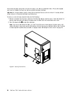
3. Lay the server on its side for easier operation.
4. Touch the static-protective package that contains the TR 500 key to any unpainted surface on the
outside of the server. Then, remove the TR 500 key from the package.
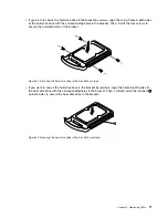
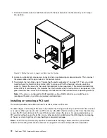
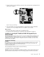
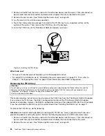
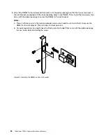
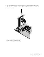
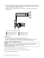
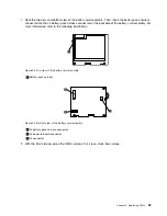
5. Install the TR 500 key to the ThinkServer RAID 500 Adapter, as shown:
Figure 48. Installing the TR 500 key
What to do next:
• To work with another piece of hardware, go to the appropriate section.
• To complete the installation, go to “Completing the parts replacement” on page 122. Then, refer to
Chapter 7 “Configuring the server” on page 143 for information about RAID configuration.
Removing the TR 500 key
Attention:
Do not open your server or attempt any repair before reading and understanding the
Safety Information
and the
Warranty and Support Information
on the
ThinkServer Documentation DVD
that came with your product, and
“Guidelines” on page 39. To obtain a copy of the publications, go to:
http://www.lenovo.com/support
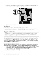
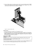
This section provides instructions on how to remove the TR 500 key from the ThinkServer RAID 500 Adapter.
If you remove the TR 500 key, the RAID 5 configuration function of the ThinkServer RAID 500 Adapter
becomes unavailable. However, the RAID 5 configuration function of the onboard SATA RAID is still available
if you have installed the RAID 5 Key on the system board. See “Installing the RAID 5 key” on page 77.
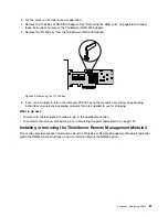
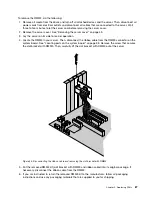
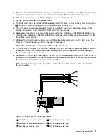
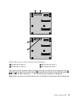
To remove the TR 500 key, do the following:
Attention:
Electrostatic discharge (ESD) can damage the TR 500 key. Always ground yourself and use a
ground strap before touching the option. Perform the following procedure at an ESD-safe workstation.
1. Remove all media from the drives and turn off all attached devices and the server. Then, disconnect all
power cords from electrical outlets and disconnect all cables that are connected to the server.
2. Remove the server cover. See “Removing the server cover” on page 43.
80
ThinkServer TD230 Hardware Maintenance Manual
Содержание and 1040
Страница 1: ...ThinkServer TD230 Hardware Maintenance Manual Machine Types 1027 1029 1039 and 1040 ...
Страница 2: ......
Страница 3: ...ThinkServer TD230 Hardware Maintenance Manual Machine Types 1027 1029 1039 and 1040 ...
Страница 16: ...10 ThinkServer TD230 Hardware Maintenance Manual ...
Страница 20: ...14 ThinkServer TD230 Hardware Maintenance Manual ...
Страница 44: ...38 ThinkServer TD230 Hardware Maintenance Manual ...
Страница 67: ...1 Press the blue button 1 to open the side door Figure 29 Opening the side door Chapter 5 Replacing FRUs 61 ...
Страница 148: ...142 ThinkServer TD230 Hardware Maintenance Manual ...
Страница 166: ...160 ThinkServer TD230 Hardware Maintenance Manual ...
Страница 168: ...162 ThinkServer TD230 Hardware Maintenance Manual ...
Страница 172: ...166 ThinkServer TD230 Hardware Maintenance Manual ...
Страница 185: ......
Страница 186: ...Part Number Printed in China 1P P N ...