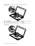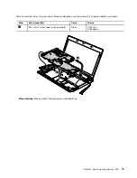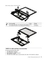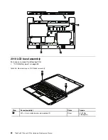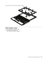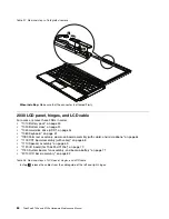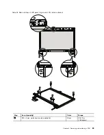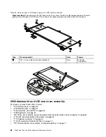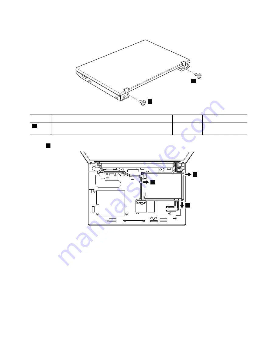
Table 24. Removal steps of LCD unit
1
1
Step
Screw (quantity)
Color
Torque
1
For ThinkPad X100e, M2 × 3 mm, wafer-head, nylon-coated (2)
For ThinkPad X120e, M2 × 4 mm, wafer-head, nylon-coated (2)
Silver
0.181 Nm
(1.85 kgfcm)
In step
2
, release all of the antenna cables from the cable guides.
2
2
2
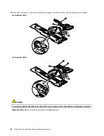
When installing:
• Make sure that you route the cables firmly as shown in this figure.
• When you route the cables, make sure that they are not subjected to any tension. Tension could cause the cables
to be damaged by the cable guides, or a wire to be broken.
78
ThinkPad X100e and X120e Hardware Maintenance Manual
Содержание 059624U
Страница 1: ...ThinkPad X100e and X120e Hardware Maintenance Manual ...
Страница 6: ...iv ThinkPad X100e and X120e Hardware Maintenance Manual ...
Страница 18: ...12 ThinkPad X100e and X120e Hardware Maintenance Manual ...
Страница 19: ...Chapter 1 Safety information 13 ...
Страница 22: ...16 ThinkPad X100e and X120e Hardware Maintenance Manual ...
Страница 26: ...20 ThinkPad X100e and X120e Hardware Maintenance Manual ...
Страница 50: ...44 ThinkPad X100e and X120e Hardware Maintenance Manual ...
Страница 54: ...48 ThinkPad X100e and X120e Hardware Maintenance Manual ...
Страница 69: ...Table 16 Removal steps of keyboard continued 3 4 5 6 7 7 8 Chapter 8 Removing and replacing a FRU 63 ...
Страница 94: ...88 ThinkPad X100e and X120e Hardware Maintenance Manual ...
Страница 120: ...LCD FRUs 1 4 3 2 5 7 6 114 ThinkPad X100e and X120e Hardware Maintenance Manual ...
Страница 132: ...126 ThinkPad X100e and X120e Hardware Maintenance Manual ...
Страница 135: ......
Страница 136: ...Part Number 63Y0640_02 Printed in 1P P N 63Y0640_02 63Y0640_02 ...

