


Page 17
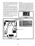
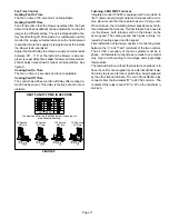
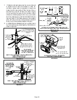
FIGURE 16
1 -
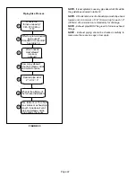
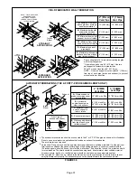
Remove thermostat demand and allow unit to cycle off.
2 -
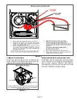
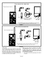
Install a tee in the negative (-) line (red tubing) and a tee in the
positive (+) line (black tubing) running from the pressure
switch to the cold end header box.
3 -
Install a manometer with hose from the negative (-) side of
the manometer to the tee installed in the negative (-) line and
with hose from the positive (+) side of the manometer to the
tee in the positive (+) line.
NOTE - Both sides of the cold end header box are negative. How
ever the (+) port reads less negative pressure than the (-) port.
4 -
Operate unit and observe manometer reading.
Readings will change as heat exchanger warms.
a. Take one reading immediately after start‐up.
b. Take a second reading after unit has reached steady
state (approximately 5 minutes). This will be the pressure
differential.
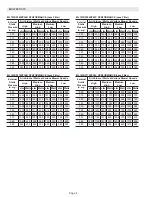
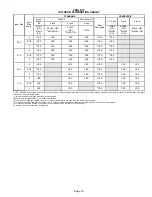
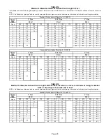
The pressure differential should be greater
than those listed in table 10.
5 -
Remove thermostat demand and allow to cycle off.
6 -
Remove manometer and tee's. Reinstall combustion air
sensing hoses to the pressure switch.
BLACK TUBING
POSITIVE
RED TUBING
NEGATIVE
Measuring Pressure Differential
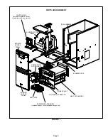
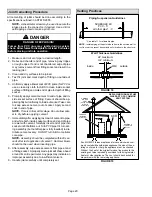
C-Blower Compartment
Blower motor (B3) and capacitor (C4), are located in the
blower compartment. The blower compartment can be ac
cessed by removing the blower access panel.
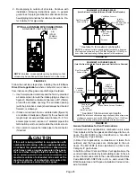
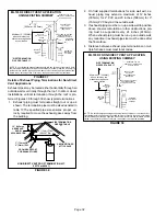
FIGURE 17
Blower Motor Housing
To Remove Blower From Unit: Disconnect Power, Remove Control
Box, Remove Bolts and Unplug Motor Wires From Control Board.
Then Slide Out Front of Unit.
MOTOR
CAPACITOR
BOLTS
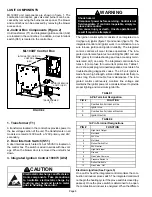
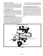
1.Blower Motor (B3) and Capacitor (C4)
All ML193DF units use single-phase direct-drive blower
motors. All motors are 120V permanent split capacitor mo
tors to ensure maximum efficiency. See SPECIFI
CATIONS table at the front of this manual for more detail.
See motor nameplate for capacitor ratings.


