


Page 25
2 - Route piping to outside of structure. Continue with
installation following instructions given in general
guide lines for piping terminations and intake and ex
haust piping terminations for direct vent sections. Re
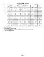
fer to table
14
for pipe sizes.
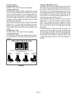
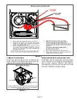
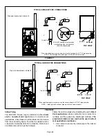
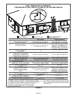
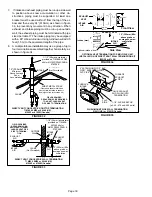
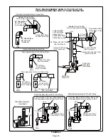
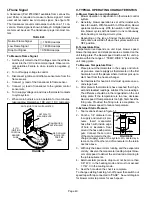
FIGURE 23
TYPICAL AIR INTAKE PIPE CONNECTIONS
NON−DIRECT VENT APPLICATIONS
AIR
INTAKE
SCREEN
(Provided)
NOTE
- Air intake screen and elbow may be rotated, so that
screen may be positioned to face forward or to either side.
Follow the next two steps when installing the unit in
Non‐
Direct Vent applications
where combustion air is taken
from indoors and flue gases are discharged outdoors
.
1
-
Use field-provided materials and the factory-provided
air intake screen to route the intake piping as shown in
figure 23. Maintain a minimum clearance of 3” (76mm)
around the air intake opening. The air intake opening
(with the protective screen) should always be directed
forward, or sideways.
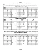
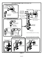
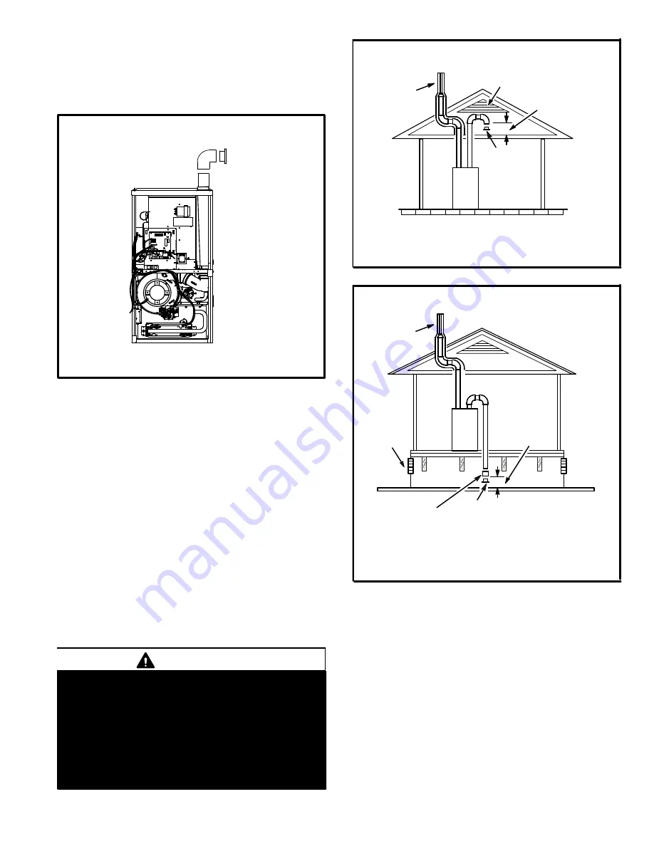
2 - If intake air is drawn from a ventilated attic (figure 24)
or ventilated crawlspace (figure 25) the exhaust vent
length must not exceed those listed in table 15. If 3” di
ameter pipe is used, reduce to 2” diameter pipe at the
termination point to accommodate the debris screen.
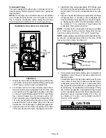
3 - Use cement to secure the intake pipe to the connector,
if desired.
CAUTION
If this unit is being installed in an application with
combustion air coming in from a space serviced by
an exhaust fan, power exhaust fan, or other device
which may create a negative pressure in the space,
take care when sizing the inlet air opening. The in
let air opening must be sized to accommodate the
maximum volume of exhausted air as well as the
maximum volume of combustion air required for
all gas appliances serviced by this space.
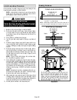
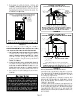
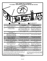
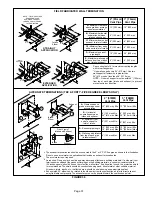
FIGURE 24
EQUIPMENT IN CONFINED SPACE
(Inlet Air from Ventilated Attic and Outlet Air to Outside)
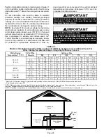
NOTE
-The inlet and outlet air openings shall each have a free area
of at least one square inch per 4,000 Btu (645mm
2
per 1.17kW) per
hour of the total input rating of all equipment in the enclosure.
Ventilation Louvers
Inlet Air
(Minimum
12 in.(305mm) Above
attic floor)
Roof Terminated
Exhaust Pipe
Furnace
*Intake Debris
Screen
(Provided)
* See table 15 for maximum vent lengths
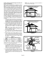
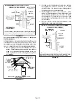
FIGURE 25
NOTE
-The inlet and outlet air openings shall each have a free area
of at least one square inch per 4,000 Btu (645mm
2
per 1.17kW) per
hour of the total input rating of all equipment in the enclosure.
EQUIPMENT IN CONFINED SPACE
(Inlet Air from Ventilated Crawlspace and Outlet Air to Outside)
Roof Terminated
Exhaust Pipe
Furnace
Ventilation
Louvers
(Crawl space)
*Intake Debris Screen Provided)
Inlet Air
(Minimum
12 in.(305mm)
Above crawl
space floor)
Coupling or
3 in. to 2 in.
Transition
(Field Provided)
* See table 15 for maximum vent lengths
General Guidelines for Vent Terminations
In Non‐Direct Vent applications, combustion air is taken
from indoors and the flue gases are discharged to the out
doors. The ML193DF is then classified as a non‐direct
vent, Category IV gas furnace.
In Direct Vent applications, combustion air is taken from
outdoors and the flue gases are discharged to the out
doors. The ML193DF is then classified as a direct vent,
Category IV gas furnace.
In both Non‐Direct Vent and Direct Vent applications, the
vent termination is limited by local building codes. In the ab
sence of local codes, refer to the current National Fuel Gas
Code ANSI Z223-1/NFPA 54 in U.S.A., and current CSA-
B149 Natural Gas and Propane Installation Codes in Can
ada for details.


