


Page 6
I-UNIT COMPONENTS
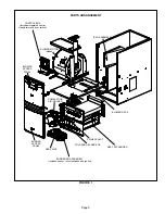
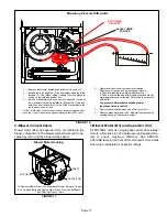
ML193DF unit components are shown in figure 1. The
combustion air inducer, gas valve and burners can be ac
cessed by removing the burner access panel. The blower
and control box can be accessed by removing the blower
access door.
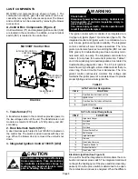
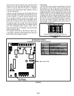
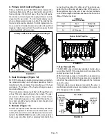
A-Control Box Components (Figure 2)
Unit transformer (T1) and integrated ignition control (A92)
are located in the control box. In addition, a door interlock
switch (S51) is located in the control box.
FIGURE 2
DOOR INTERLOCK
SWITCH (S51)
INTEGRATED IGNITION
CONTROL
(A92)
TRANSFORMER
(T1)
ML193DF Control Box
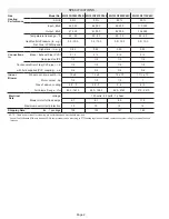
1. Transformer (T1)
A transformer located in the control box provides power to
the low voltage section of the unit. The transformers on all
models are rated at 40VA with a 120V primary and 24V
secondary.
2. Door Interlock Switch (S51)
A door interlock switch rated 14A at 120VAC is located on
the control box. The switch is wired in series with line volt
age. When the blower door is removed the unit will shut
down.
3. Integrated Ignition Control 100973 (A92)
CAUTION
Electrostatic discharge can affect elec
tronic components. Take precautions
to neutralize electrostatic charge by
touching your hand and tools to metal
prior to handling the control.
WARNING
Shock hazard.
Disconnect power before servicing. Control is not
field repairable. If control is inoperable, simply re
place entire control.
Can cause injury or death. Unsafe operation will
result if repair is attempted.
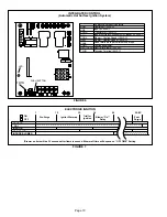
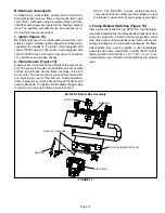
The ignition control system consists of an integrated con
trol (figure 4) ignitor (figure 10) and sensor (figure 10). The
integrated control and ignitor work in combination to en
sure furnace ignition and ignitor durability. The integrated
control, controls all maor furnace operations. The inte
grated control also features two LED lights (DS1 red and
DS2 green) for troubleshooting and two accessory termi
nals rated at (1) one amp. The integrated control also fea
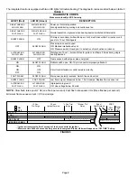
tures a (3) amp fuse for overcurrent protection. Tables 1
and 2 show jack plug terminal designations. See table 3 for
troubleshooting diagnostic codes. The 95 volt ignitor is
made from a high strength, silicon nitride material that pro
vides long life and trouble free maintenance. The inte
grated control continuously monitors line voltage and
maintains the ignitor power at a consistent level to provide
proper lighting and maximum ignitor life.
TABLE 1
4-Pin Terminal Designation
PIN #
FUNCTION
1
Combustion Air Inducer Line
2
Ignitor Line
3
Combustion Air Inducer Neutral
4
Ignitor Neutral
TABLE 2
12-Pin Terminal Designations
PIN #
FUNCTION
1
High Limit Output
2
Not Used
3
24V Line
4
Not Used
5
Rollout Switch Out
6
24V Neutral
7
High Limit Input
8
Ground
9
Gas Valve Common
10
Pressure Switch In
11
Rollout Switch In
12
Gas Valve Out
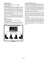
Electronic Ignition (See Figure 5)
On a call for heat the integrated control monitors the com
bustion air inducer prove switch. The integrated control will
not begin the heating cycle if the prove switch is closed (by-
passed). Once the prove switch is determined to be open,
the combustion air inducer is energized. When the differen


