


Page 41
VI-MAINTENANCE
WARNING
ELECTRICAL SHOCK, FIRE,
OR EXPLOSION HAZARD.
Failure to follow safety warnings exactly could result
in dangerous operation, serious injury, death or
property damage.
Improper servicing could result in dangerous opera
tion, serious injury, death, or property damage.
Before servicing, disconnect all electrical power to
furnace.
When servicing controls, label all wires prior to dis
connecting. Take care to reconnect wires correctly.
Verify proper operation after servicing.
At the beginning of each heating season, system should be
checked as follows by a qualified service technician:
Blower
Check the blower wheel for debris and clean if necessary.
The blower motors are prelubricated for extended bearing
life. No further lubrication is needed.
WARNING
The blower access panel must be securely in place
when the blower and burners are operating. Gas
fumes, which could contain carbon monoxide, can
be drawn into living space resulting in personal inju
ry or death.
Filters
All air filters are installed external to the unit. Filters should
be inspected monthly. Clean or replace the filters when
necessary to ensure proper furnace operation. Table 24
lists recommended filter sizes.
IMPORTANT
If a highefficiency filter is being installed as part of
this system to ensure better indoor air quality, the fil
ter must be properly sized. Highefficiency filters
have a higher static pressure drop than standardef
ficiency glass/foam filters. If the pressure drop is too
great, system capacity and performance may be re
duced. The pressure drop may also cause the limit to
trip more frequently during the winter and the indoor
coil to freeze in the summer, resulting in an increase
in the number of service calls.
Before using any filter with this system, check the
specifications provided by the filter manufacturer
against the data given in the appropriate Lennox
Product Specifications bulletin. Additional informa
tion is provided in Service and Application Note
ACC002 (August 2000).
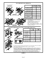
TABLE 24
Furnace
Cabinet Width
Filter Size
16 x 25 x 1 (1)
17-1/2”
21”
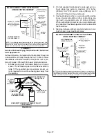
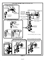
Exhaust and air intake pipes
Check the exhaust and air intake pipes and all connections
for tightness and to make sure there is no blockage.
NOTE
- After any heavy snow, ice or frozen fog event the
furnace vent pipes may become restricted. Always check
the vent system and remove any snow or ice that may be
obstructing the plastic intake or exhaust pipes.
Electrical
1 - Check all wiring for loose connections.
2 - Check for the correct voltage at the furnace (furnace
operating). Correct voltage is 10%
3 - Check amp-draw on the blower motor with blower ac
cess panel in place.
Motor Nameplate__________Actual__________
Winterizing and Condensate Trap Care
1 - Turn off power to the furnace.
2 - Have a shallow pan ready to empty condensate water.
3 - Remove the clean out cap from the condensate trap
and empty water. Inspect the trap then reinstall the
clean out cap.
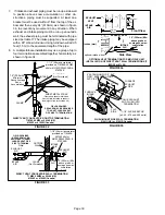
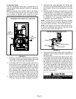
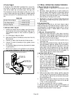
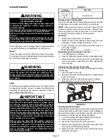
Condensate Hose Screen (Figure 52)
Check the condensate hose screen for blockage and clean
if necessary.
1 - Turn off power to the unit.
2 - Remove hose from cold end header box. Twist and pull
screen to remove.
3 - Inspect screen and rinse with tap water if needed.
4 - Reinstall screen and turn on power to unit.
FIGURE 52
Condensate Hose Screen
Hose
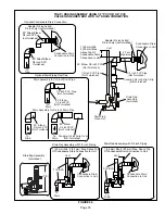
Cleaning Heat Exchanger
If cleaning the heat exchanger becomes necessary, follow
the below procedures and refer to figure 1 when disassem
bling unit. Use papers or protective covering in front of fur
nace while removing heat exchanger assembly.
1 - Turn off electrical and gas supplies to the furnace.
2 - Remove the furnace access panels.
3 - Disconnect the 2 wires from the gas valve.
4 - Remove gas supply line connected to gas valve. Re
move gas valve/manifold assembly.
5 - Remove sensor wire from sensor. Disconnect 2‐pin
plug from the ignitor.


