


Page 8
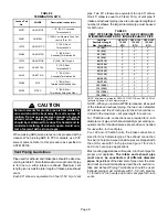
TABLE 4
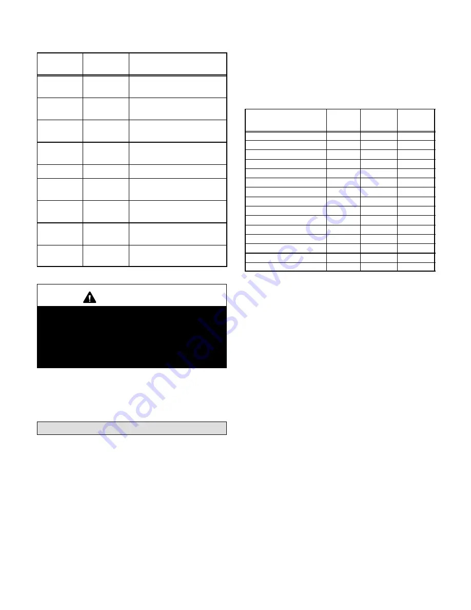
TERMINATION KITS
Lennox Part
No.
Kit LB#
Description-Inches (mm)
60G77
LB-49107CE
1-1/2" (50.8) Concentric
Termination Kit
33K97
LB-87942
3" (50.8) Low Pressure Drop ConĆ
centric Term. Kit
15F75
LB-49107CC
2" (50.8) Roof
Termination Kit
22G44
LB-49107CD
2" (50.8) Wall
Assembly Termination Kit
15F74
LB-49107CB
2" (50.8) Wall Ring Kit
44J41
LB-65678A
3" (76.2) Roof
Termination Kit
44J40
LB-65701A
3" (76.2) Wall
Assembly Termination Kit
30G28
WTK
2" (50.8) Wall
Termination Extended Vent
30G79
WTKX
2" (50.8) Wall
Termination Extension Riser
CAUTION
Solvent cements for plastic pipe are flammable liqĆ
uids and should be kept away from all sources of
ignition. Do not use excessive amounts of solvent
cement when making joints. Good ventilation
should be maintained to reduce fire hazard and to
minimize breathing of solvent vapors. Avoid conĆ
tact of cement with skin and eyes.
When making ABS joints, pieces can be prepared with a
cleaner. When joining ABS to PVC materials, use PVC
solvent cement. Refer to this procedure as specified in
ASTM D3138.
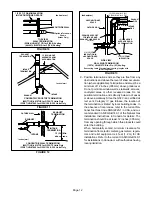
Vent Piping Guidelines
Pipe used for exhaust and intake lines should be sized acĆ
cording to table 5. Note that maximum length of vent pipe
is for one run; either intake or exhaust. Maximum vent
length given is
not
the total length of intake plus exhaust
vents.
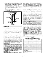
Each 90° elbow is equivalent to 5 feet (1.52 m) of vent
pipe. Two 45° elbows are equivalent to one 90° elbow.
One 45° elbow is equal to 2.5 feet (.76 m) of vent pipe. If
intake and exhaust piping runs are not equal in length and
number of elbows, the larger diameter pipe must be used
for both runs.
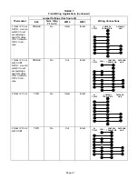
TABLE 5
VENT PIPE SIZING TABLE FOR G32V FURNACES
MINIMUM DIAMETER OF INTAKE/EXHAUST PIPE
Vent Pipe
Equivalent Length
Max. Feet (Meters)
G32V-75
75,000
BTU
G32V-100
100,000
BTU
G32V-125
125,000
BTU
15 (4.57)
2"
2"
2"
20 (6.10)
2"
2"
3"
25 (7.62)
2"
2"
3"
30 (9.14)
2"
3"
3"
40 (12.19)
2"
3"
3"
50 (15.24)
2"
3"
3"
55 (16.76)
2"
3"
3"
60 (18.29)
3"
3"
3"
70 (21.34)
3"
3"
3"
80 (24.38)
3"
3"
3"
90 (27.43)
3"
3"
3"
100 (30.48)
3"
3"
3"
110 (33.53)
3"
3"
3"
120 (36.58)
3"
3"
3"
130 (39.62)
3"
3"
--
NOTE - Minimum vent pipe for G32V-75, G32V-100, and G32V-125 is 5
feet with 2 elbows of 2-inch diameter pipe.
NOTE - When you install a WTKX termination kit as part
of the intake and exhaust piping, the two 2-inch diameter
90° elbows and the 27 inch pipe (in the kit) should be inĆ
cluded in the maximum vent pipe length for each run.
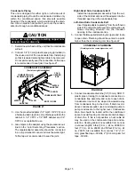
For 75 kBtuh units
, connections are provided for 2-inch
diameter vent pipe which should satisfy most venting reĆ
quirements. No transition pieces are provided or needed
for use with 2-inch vent pipe.
For -100 and -125 kBtuh units,
the intake connection is
sized for 3-inch diameter pipe. The exhaust connection
has a 2-inch nipple.
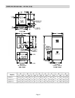
A pipe transition piece is shipped with
the unit for use with 3-inch pipe. See figure 7 for 2-inch
and 3-inch vent pipe applications.
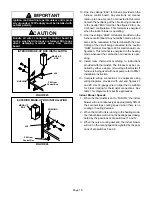
Most venting applications will require 3-inch vent pipe for
proper unit operation.
The intake and exhaust pipe
must never be constructed of different diameter
pipes.
Regardless of the diameter of pipe used, the stanĆ
dard roof and wall terminations described in section
InĆ
take and Exhaust Piping Terminations
should be used.
Exhaust piping must terminate with 1-1/2 inch pipe for
1-1/2 inch or 2 inch vents and 2-inch vent pipe for 3-inch
vents.