


Page 7
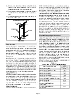
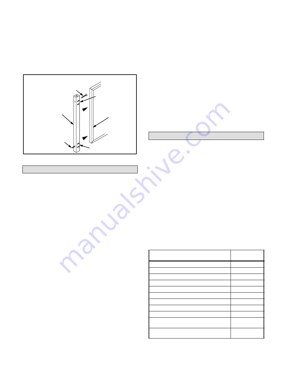
4 - Position filter door on end of filter so that the thumb
tab side of the filter door is away from the furnace.
Squeeze thumb tabs to secure filter to door.
5 - Guide filter and filter door into the filter rack installed
on side of furnace. Push door into filter rack until se-
cure.
6 - To remove filter, pull filter door pins until door is re-
leased from filter rack.
FIGURE 6
FILTER DOOR ASSEMBLY
FILTER DOOR
PIN
FILTER DOOR
FILTER
FILTER DOOR
PIN
TAB
TAB
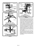
Duct System
Use industry-approved standards to size and install the
supply and return air duct system. This will result in a quiet
and low-static system that has uniform air distribution. If
the G32V unit is being installed as a replacement for an
existing furnace, the existing supply and return air duct
system should be evaluated to make sure that it is approĆ
priately sized.
The total external static pressure (ESP) should not exĆ
ceed 0.8" w.c. The ESP calculation should include presĆ
sure losses caused by electronic air cleaners, filters,
cooling coils, the duct system, registers and grilles. A
properly sized duct system will help to optimize efficiency
and reliability and to minimize sound levels. Operation of
a G32V unit outside of its specified static pressure range
will result in poor performance and will reduce the useful
life-expectancy of the product and its components.
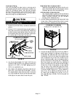
Supply Air Plenum
Furnaces installed without a cooling coil require the installaĆ
tion of a removable access panel in the supply air duct. The
access panel should be large enough to permit inspection
(either by smoke or reflected light) of the heat exchanger for
leaks after installation. The furnace access panel must alĆ
ways be in place when the furnace is operating and it must
not allow leaks into the supply air duct system.
Return Air Plenum
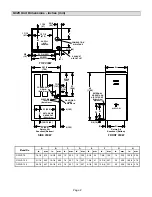
See dimension illustration for proper return air duct size.
NOTE - For bottom return air, return air duct should be seĆ
cured to the unit using rivets or S-locks. For side return
air, secure return air duct to filter rack using screws. When
using screws, take care to avoid interference with the filĆ
ter which may cause improper filtration.
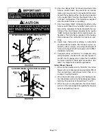
The return air must not be drawn from a room where
another gas appliance (ie., a water heater) is
installed.
Even though this furnace draws its combusĆ
tion air from outside of the structure, other gas apĆ
pliances that share a utility room may not. When return
air is drawn from a room, a negative pressure is created
in the room. If a gas appliance is operating in a room
with negative pressure, the flue products can be pulled
back down the vent pipe and into the room. This reverse
flow of the flue gas may result in incomplete combustion
and the formation of carbon monoxide gas. This toxic
gas might then be distributed through the house by the
furnace duct system.
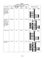
Pipe & Fittings Specifications
All pipe, fittings, primer and solvent cement must conform
with American National Standard Institute and the AmeriĆ
can Society for Testing and Materials (ANSI/ASTM) stanĆ
dards. The solvent shall be free flowing and contain no
lumps, undissolved particles or any foreign matter that
adversely affects the joint strength or chemical resistance
of the cement. The cement shall show no gelation, stratifiĆ
cation, or separation that cannot be removed by stirring.
Refer to table 3 for approved piping and fitting materials.
Primers and solvents must meet ASTM specifications.
PVC primer is specified in ASTM F 656. Use PVC solvent
cement as specified in ASTM D 2564 and ABS solvent
cement as specified in ASTM D 2235. Low temperature
solvent cement is recommended. Metal or plastic strapĆ
ping may be used for vent pipe hangers.
Table 4 lists the available exhaust termination kits. All
Lennox vent terminations are PVC.
TABLE 3
PIPING AND FITTINGS SPECIFICATIONS
PIPE & FITTING MATERIAL
ASTM
SPECIFICATION
Schedule 40 PVC (Pipe)
D1785
Schedule 40 PVC (Cellular Core Pipe)
F891
Schedule 40 PVC (Fittings)
D2466
Schedule 40 CPVC (Pipe)
F441
Schedule 40 CPVC (Fittings)
F438
SDR-21 PVC (Pipe) or SDR-26 PVC (Pipe)
D2241
SDR-21 CPVC (Pipe) or SDR-26 CPVC (Pipe)
F442
Schedule 40 ABS (Pipe)
D1527
Schedule 40 ABS (Fittings)
D2468
ABS-DWV (Drain Waste & Vent)
(Pipe & Fittings)
D2661
PVC-DWV (Drain Waste & Vent -
Pipe & Fittings)
D2665