Lennox G32V3-75 Скачать руководство пользователя страница 5

Page 5

NOTE  -  G32V  series  units  must  not  be  used  as  a

construction  heater  during  any  phase  of  construction.
Very low return air temperatures, harmful vapors and misĆ

placement of the filters will damage the unit and lower its

efficiency.

The G32V furnace may be installed in alcoves, closĆ

ets, attics, basements, garages and utility rooms in

the upflow position.

General

The G32V is an upflow gas furnace which is factory-

equipped for use with natural gas.

 A changeover kit is

necessary if the furnace is to be used with L.P. gas. These

instructions are intended as a general guide and do not

supersede local codes in any way.  Consult  authorities

having jurisdiction before installation.

Shipping and Packing List

 1 - Assembled G32V furnace
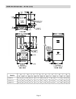
 1 - 3 inch x 2 inch vent transition piece (-100, -125 

units only)

 1 - Bag assembly containing:

1 - Filter

1 - External filter rack for side return air application

 1 - Bag assembly containing:

1 - Electrical make-up box with cover and 

     grounding screw

4 - Thread-forming make-up box screws

1 - Green ground wire

1 - Wiring harness

1 - Snap bushing

2 - Filter clips

1 - Condensate drain pipe adapter

1 - Condensate plug

4 - Wire nuts

2 - Lockwashers and screws

8 - Self-tapping screws

2 - Filter door pins

1 - Grounding label

1 - Wire tie

Shipping Damage

Check equipment for shipping damage. If you find any

damage, immediately contact the last carrier.

WARNING

Improper  installation, adjustment, alteration, serĆ

vice or maintenance can cause property damage,

personal injury or loss of life. Installation and serĆ

vice must be performed by a qualified installer, serĆ

vice agency or the gas supplier.

CAUTION

As with any mechanical equipment, personal injuĆ

ry can result from contact with sharp sheet metal

edges. Be careful when you handle this equipment.

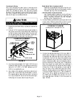
Installation - Setting Equipment

Select a location that allows for required clearances listed
on the unit rating plate. Also consider gas supply connecĆ

tions, electrical supply, vent connection and installation
and service clearances [24 inches (610 mm) at unit front].

The furnace must be level.

CAUTION

G32V unit should not be installed in areas normally

subject to freezing temperatures.

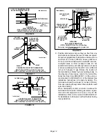
Return Air Opening Guidelines

WARNING

Improper installation of unit can result in personal

injury  or  death.  Combustion  and  flue  products

must never be allowed to enter the return air sysĆ

tem  or  air  in  the  living  space.  Use  sheet metal

screws and joint tape to seal return air system to

furnace.

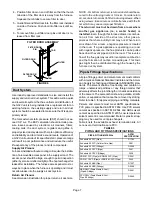
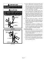
In platform installations with furnace return, the

furnace should be sealed airtight to the return air

plenum. A door must never be used as a portion of

the return air duct system. The base must provide

a stable support and an airtight seal to the furnace.

Allow absolutely no sagging, cracks, gaps, etc.

For no reason should return and supply air duct

systems ever be connected to or from other heat-

ing devices such as a fireplace or stove, etc. Fire,

explosion, carbon monoxide poisoning, personal

injury and/or property damage could result.

WARNING

The blower access panel must be securely in place

when  the  blower and burners are operating. Gas

fumes, which could contain carbon monoxide, can

be drawn into living space resulting in personal inĆ

jury or death.

Return air can be brought in either side or at the bottom of
the unit. Scribe lines show the outline of each side and the

bottom return air opening.

Содержание G32V3-75

Страница 1: ...mation 32 Other Unit Adjustments 32 Service 32 Repair Parts List 35 Integrated Control Board Diagnostic Codes 35 Troubleshooting 36 Start Up Performance Check List 42 WHAT TO DO IF YOU SMELL GAS Do no...

Страница 2: ...DRAIN Both Sides EXHAUST AIR OUTLET COMBUSTION AIR INTAKE 21 3 4 552 7 3 8 187 23 3 4 603 25 635 5 8 16 H G 5 8 16 EXTERNAL SIDE RETURN AIR FILTER KIT Either Side Optional 23 584 D Return Air Knockout...

Страница 3: ...EAT EXCHANGER ASSEMBLY CONTROL VOLTAGE CIRCUIT BREAKER WARM HEADER COLLECTOR BOX COLD HEADER COLLECTOR BOX TWO SPEED COMBUSTION AIR INDUCER COMBUSTION AIR ORIFICE BLOWER ACCESS DOOR BURNER ACCESS PANE...

Страница 4: ...AN CGA B149 1 and B149 2 standards When the furnace is used with cooling units it shall be installed in parallel with or on the upstream side of cool ing units to avoid condensation in the heating com...

Страница 5: ...ncy or the gas supplier CAUTION As with any mechanical equipment personal inju ry can result from contact with sharp sheet metal edges Be careful when you handle this equipment Installation Setting Eq...

Страница 6: ...SIZE REQUIREMENTS UNIT MODEL NUMBER FILTER PART NUMBER FILTER SIZE G32V 75 31J81 14 inches x 25 inches 356 x 635 mm G32V 100 G32V 125 P 8 7831 20 inches x 25 inches 508 x 635 mm Bottom Return Air Appl...

Страница 7: ...errack usingscrews When using screws take care to avoid interference with the fil ter which may cause improper filtration The return air must not be drawn from a room where another gas appliance ie a...

Страница 8: ...umber of elbows the larger diameter pipe must be used for both runs TABLE 5 VENT PIPE SIZING TABLE FOR G32V FURNACES MINIMUM DIAMETER OF INTAKE EXHAUST PIPE Vent Pipe Equivalent Length Max Feet Meters...

Страница 9: ...mpleted within 20 se conds after last application of cement Hammer blows should not be used when inserting pipe 8 After assembly wipe excess cement from pipe at end of fitting socket A properly made j...

Страница 10: ...lo cated and other spaces of the building Turn on clothes dryers and any appliances not connected to the common venting system Turn on any exhaust fans such as range hoods and bathroom exhausts so th...

Страница 11: ...erioration NOTE During extremely cold temperatures below approximately 20 F 6 67 C units with long runs of vent pipe through unconditioned space even when in sulated may form ice in the exhaust termin...

Страница 12: ...L Inches mm SIDE VIEW WALL RING TERMINATION 15F74 LB 49107CB for 2 in 51 Venting INTAKE PIPE EXHAUST PIPE 9 Position termination ends so they are free from any obstructions and above the level of snow...

Страница 13: ...trapping or a large wire tie 11 In areas where piping penetrates joists or interior walls hole must be large enough to allow clearance on all sides of pipe as it passes through the center of the hole...

Страница 14: ...h 1 2 inch 13 mm foam insulation If intake and ex haust pipes are reversed slit and remove foam insulation and reapply to other vent Exhaust vent must be insulated Front View Side View OUTSIDE WALL In...

Страница 15: ...r and must be water tight Teflon tape is recommended to seal the joint Right Hand Side Condensate Exit Install the nipple adapter assembly from the out side of the cabinet and insert the adapter into...

Страница 16: ...ace The piping must be supported at proper inter vals every 8 to 10 feet 2 44 to 3 01 m using suit able hangers or straps A drip leg should be installed in vertical pipe runs to the unit 5 In some loc...

Страница 17: ...ted control ELECTROSTATIC DISCHARGE ESD Precautions and Procedures CAUTION Electrostatic discharge can affect electronic com ponents Take precautions during furnace installa tion and service to protec...

Страница 18: ...leg of the circuit being connected to the neutral HUM terminal See figure 29 for control board con figuration This terminal is energized in the heating mode whenever the combustion air inducer is ope...

Страница 19: ...Page 19 TYPICAL G32V SCHEMATIC WIRING DIAGRAM FIGURE 27...

Страница 20: ...ring Connections 1 Heat 1 Cool NOTE Use dip switch 3 to set second stage heat ON delay ON 10 minutes OFF 15 min utes SINGLE Yes Intact Intact S1 T STAT CONTROL TERM STRIP OUTDOOR UNIT 1 Heat 1 Cool wi...

Страница 21: ...s OFF 15 min utes SINGLE No Intact Intact S1 T STAT CONTROL TERM STRIP OUTDOOR UNIT 1 Heat 2 Cool with CCB1 NOTE Use dip switch 3 to set second stage heat ON delay ON 10 minutes OFF 15 min utes SINGLE...

Страница 22: ...outdoor unit and thermostat made at FM21 control board per FM21 instructions NOTE Remove Y1 Y2 jumper for two stage cooling Harmony Application 2 Heat 1 Cool TWO Yes Cut Intact TEMP MOD SWITCH CONTRO...

Страница 23: ...l break and remake thermostat demand to the furnace and auto matically reset the control to relight the furnace Thermostat Selection Jumper E20 This unit may be used with either a single stage or two...

Страница 24: ...to better suit the application The table below provides blower speed adjustments that will result from different switch settings Refer to tables 13 and14 for corresponding cfm values TABLE 10 Blower...

Страница 25: ...two speed outdoor unit On Board Jumper W951 On board jumper W951 which connects terminals R and O on the integrated control board must be cut when the furnace is installed in applications which inclu...

Страница 26: ...y 850 cfm 400 L s for all positions TABLE 14 G32V5 100 125 BLOWER MOTOR PERFORMANCE 0 0 to 0 8 w g 0 through 200 Pa External Static Pressure Range Blower Speed Adjustment Settings Switches 5 and 6 Coo...

Страница 27: ...atically lights the burner Do not try to light the burner by hand 5 Remove unit access panel 6 Turn gas valve knob to OFF position See figure 30 7 Wait five 5 minutes to clear out any gas If you then...

Страница 28: ...Thermostat Selection Jumper E20 in Single Stage Position NOTE In these applications two stage heat will be initi ated by the integrated control if heating demand has not been satisfied after the field...

Страница 29: ...ow er speed immediately increases to the COOL CFM to hasten the end of the cycle Call for cooling after call for humidity None Humidity level above set point Demand initiated Off Dehumidification mode...

Страница 30: ...evel rises slightly 1 above setpoint Demand initiated High 77 74 of HIGH COOL Blower immediately changes speed in response to thermostat demand demand Y2 No demand Acceptable High HIGH COOL Call for 1...

Страница 31: ...stment NOTE Pressure test adaptor kit 10L34 is available from Lennox to facilitate manifold pressure measure ment 1 Connect test gauge to outlet tap on gas valve 2 Disconnect pressure sensing hose fro...

Страница 32: ...me by observation Flame should be predominantly blue and strong in appearance Check burner flame periodically to ensure proper opera tion Service WARNING Disconnect power before servicing unit CAUTION...

Страница 33: ...tibule panel and heat exchanger assembly to cabinet Remove heat exchanger 21 Back wash heat exchanger with soapy water solu tion or steam If steam is used it must be below 275 F 135 C 22 Thoroughly ri...

Страница 34: ...ckage caused by foreign matter Remove any blockage 14 Reinstall ignitor and sensor bracket assemblies on burners NOTE Install the ignitor on the opposite side of the burner from the metal button protr...

Страница 35: ...limit or rollout limit switch open Limits must close within 3 minutes or unit goes into 1 hour Watchguard OFF SLOW FLASH Low fire pressure switch open OR Blocked inlet exhaust vent OR Low fire pressu...

Страница 36: ...H DS 2 SIMULTANEOUS FAST FLASH YES PRIMARY LIMIT SWITCH CLOSED YES NO COMBUSTION AIR INDUCER OFF INDOOR BLOWER ON HAS PRIMARY LIMIT RESET WITHIN 3 MINUTES DS1 SLOW FLASH DS2 ON ON OFF LED ON HEAT LED...

Страница 37: ...R IS REPLACED OR RECONNECTED DS1 AND DS2 ALTERNATING FAST FLASH YES AT END OF IGNITOR 20 SECOND WARM UP PERIOD 4 SECOND TRIAL FOR IGNITION GAS VALVE OPENS IGNITOR ENERGIZED DURING 4 SECOND TRIAL UNTIL...

Страница 38: ...INDOOR BLOWER OFF AFTER DELAY DS1 OFF DS 2 SLOW FLASH ON OFF LED OFF HEAT LED ON NO YES C FIRST STAGE HEAT DEMAND SATISFIED DS1 AND DS2 SIMULTANEOUS SLOW FLASH GAS VALVE OFF COMBUSTION AIR INDUCER OF...

Страница 39: ...D IS SATISFIED A FIVE 5 MINUTE WAIT PERIOD IS INITIATED BEFORE RETRY WERE 5 ATTEMPTS MADE FOR SECOND STAGE HEAT YES NO SEE BOX C FIRST STAGE HEAT DEMAND SATISFIED HEAT DEMAND SATISFIED DS1 AND DS2 SIM...

Страница 40: ...OLTS LOW VOLTAGE SIGNAL AT DS HOLDS UNTIL VOLTAGE RISES ABOVE 75 VOLTS NO YES NO SIGNAL IMPROPER GROUND AT DS SIGNAL HOLDS UNTIL UNIT IS PROPERLY GROUNDED INDOOR BLOWER ENERGIZED ON FIRST STAGE COOL S...

Страница 41: ...TCHES TO LOW HEAT SPEED FIRST STAGE HEAT DEMAND SATISFIED YES NO THERMOSTAT CALLS FOR SECOND STAGE HEAT YES INDOOR BLOWER SWITCHES TO HIGH HEAT SPEED AFTER 30 SECOND RECOGNITION PERIOD SECOND STAGE HE...

Страница 42: ...Heating Section Thermostat Heat Anticipator Setting Thermostat Level Fuel Type Natural Gas Blower Motor Amps Blower Motor H P Gas Piping Connections Tight Leak Tested Proper Draft State Blower OFF De...

Отзывы: