


Page 1
05/02
*2P0502*
504,564M
*P504564M*
RETAIN THESE INSTRUCTIONS
FOR FUTURE REFERENCE
2002 Lennox Industries Inc.
Dallas, Texas, USA
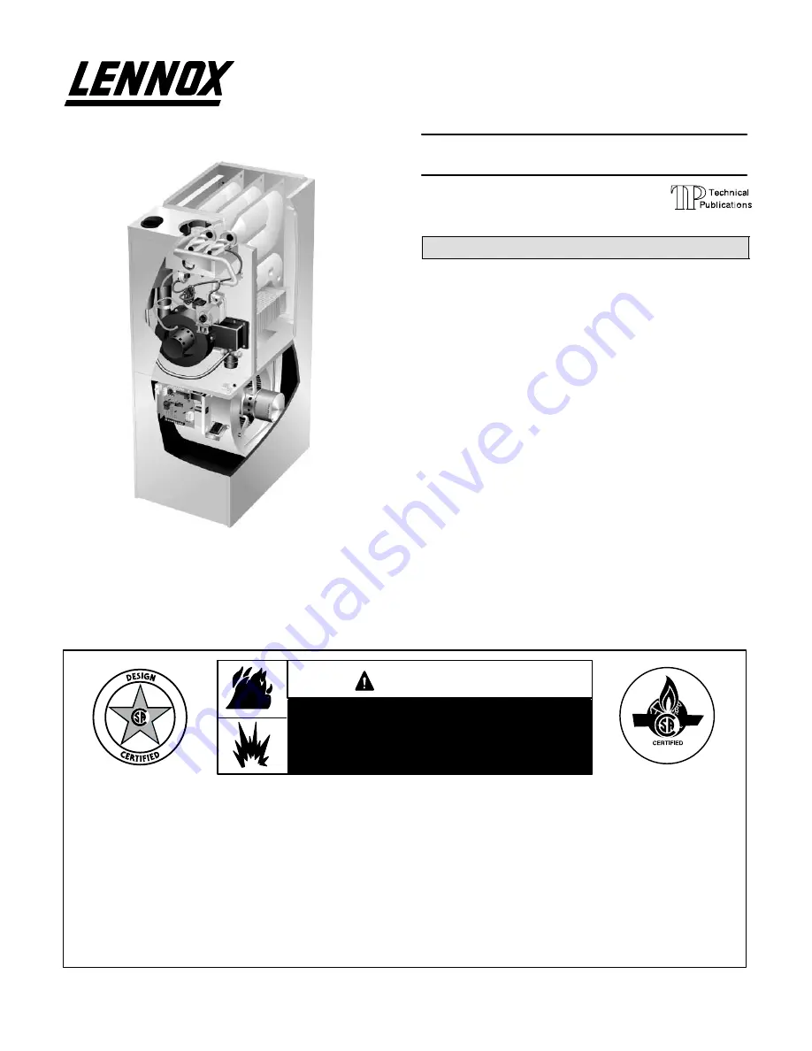
INSTALLATION
INSTRUCTIONS
G32V SERIES UNITS
GAS UNITS
504,564M
5/2002
Supersedes 504,468M
Table of Contents
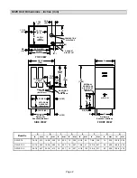
G32V Unit Dimensions- inches (mm)
2
. . . . . . . . . . . .
G32V Parts Arrangement
3
. . . . . . . . . . . . . . . . . . . . . .
Safety Instructions
4
. . . . . . . . . . . . . . . . . . . . . . . . . . . .
General
5
. . . . . . . . . . . . . . . . . . . . . . . . . . . . . . . . . . . . .
Installation - Setting Equipment
5
. . . . . . . . . . . . . . . .
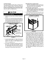
Return Air Opening Guidelines
5
. . . . . . . . . . . . . . . . .
Filter & Filter Assembly
6
. . . . . . . . . . . . . . . . . . . . . . .
Duct System
7
. . . . . . . . . . . . . . . . . . . . . . . . . . . . . . . . .
Pipe & Fittings Specifications
7
. . . . . . . . . . . . . . . . . .
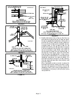
Vent Piping Guidelines
8
. . . . . . . . . . . . . . . . . . . . . . . .
Joint Cementing Procedure
9
. . . . . . . . . . . . . . . . . . . .
Venting Practices
9
. . . . . . . . . . . . . . . . . . . . . . . . . . . . .
Gas Piping
16
. . . . . . . . . . . . . . . . . . . . . . . . . . . . . . . . .
Electrical
17
. . . . . . . . . . . . . . . . . . . . . . . . . . . . . . . . . . .
Integrated Control Board Settings
23
. . . . . . . . . . . . .
Unit Start-Up
27
. . . . . . . . . . . . . . . . . . . . . . . . . . . . . . .
Heating Sequence of Operation
27
. . . . . . . . . . . . . . .
Gas Pressure Adjustment
31
. . . . . . . . . . . . . . . . . . . .
High Altitude Information
32
. . . . . . . . . . . . . . . . . . . . .
Other Unit Adjustments
32
. . . . . . . . . . . . . . . . . . . . . .
Service
32
. . . . . . . . . . . . . . . . . . . . . . . . . . . . . . . . . . . .
Repair Parts List
35
. . . . . . . . . . . . . . . . . . . . . . . . . . . .
Integrated Control Board Diagnostic Codes
35
. . . . .
Troubleshooting
36
. . . . . . . . . . . . . . . . . . . . . . . . . . . . .
Start-Up & Performance Check List
42
. . . . . . . . . . . .
WHAT TO DO IF YOU SMELL GAS:
Do not store or use gasoline or other flamĆ
mable vapors and liquids in the vicinity of
this or any other appliance.
Installation and service must be performed
by a qualified installer, service agency or
the gas supplier.
Do not try to light any appliance.
Do not touch any electrical switch; do not use any
phone in your building.
Immediately call your gas supplier from a neighbor's
phone. Follow the gas supplier's instructions.
If you cannot reach your gas supplier, call the
fire department.
Extinguish any open flames.
If the information in this manual is not
followed exactly, a fire or explosion
may result causing property damage,
personal injury or death.
WARNING
Leave the building immediately.
Litho U.S.A.