


Page 6
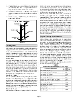
Bottom Return Air Applications
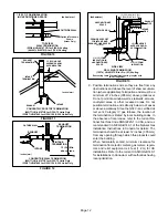
If return air is to terminate through the floor under the furĆ
nace, a direct, airtight and sealed connection must be
made to the bottom of the furnace.
1 - Cut opening in floor or platform. Using knockouts
provided, cut bottom of base panel. See figure 2.
FIGURE 2
KNOCKOUT PATTERN FOR BOTTOM
RETURN AIR APPLICATION
FIGURE 3
G32V UNIT
RETURN AIR
PLENUM
PROPERLY
SIZED FLOOR
OPENING
BOTTOM RETURN AIR APPLICATION
2 - Bend a flange on return air plenum and lower into
floor or platform opening. See figure 3.
3 - Position unit over return air opening. Seal unit air
tight with return air plenum.
NOTE - Be careful not to damage insulation. Check for
tight seal.
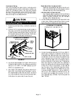
Side Return Air Applications
For installations where the return air is taken from a return
air drop, unit may be installed using either the left or right
side of furnace.
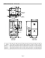
For side return air applications, cut the furnace cabinet at
the dimensions given in the unit dimensions graphic. EmĆ
bossed corners are pro-vided on both cabinet sides for reĆ
turn air opening location.
Filter & Filter Assembly
A filter and an external filter rack for use in side return air
applications are shipped with the unit.
A filter must be in
place anytime the unit is in operation.
TABLE 2
FILTER SIZE REQUIREMENTS
UNIT MODEL
NUMBER
FILTER PART
NUMBER
FILTER SIZE
G32V-75
31J81
14 inches x 25 inches
(356 x 635 mm)
G32V-100
G32V-125
P-8-7831
20 inches x 25 inches
(508 x 635 mm)
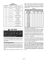
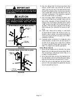
Bottom Return Air Applications
1 - Remove blower access panel.
2 - Install filter clips, provided with unit, by slipping
folded section of clip on edge of bottom opening. See
figure 4.
FIGURE 4
BOTTOM RETURN FILTER INSTALLATION
FURNACE
BASE BOTTOM
REAR FILTER CLIP
RETURN AIR OPENING
SIDE FILTER CLIPS (2)
FURNACE
FRONT
FURNACE
BACK
3 - Place filter in bottom of blower compartment beneath
rear filter clip. Press down on filter sides. Filter clips
flex allowing filter to snap into place.
4 - To remove filter, press clip and pull filter up and out.
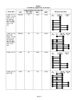
Side Return Air Applications
1 - Align filter rack opening with the inside edge of the
side return opening. Bottom of rack should be
approximately 1 inch (25 mm) from the bottom and 3
inches (76 mm) from the front of the unit.
2 - Screw filter rack into place with the eight self drill, self
tap screws provided. See figure 5.
3 - Push filter door pins through the two holes in filter
door from the inside of the uĆchannel. See figure 6.
FIGURE 5
SIDE RETURN FILTER INSTALLATION
RETURN
AIR
OPENING
12 in. (305) for
14 in. (356) Filter
18 in. (457) for
20 in. (508) Filter
1-15/16 in.
(49)
BLOWER DECK
15/16 in
(24)
CABINET BASE BOTTOM
RETURN AIR
PLENUM SIZE
12-3/4 in X 23-1/2 in (324 X
597) for 14 in (356) Filter
18-3/4 in. x 23-1/2 in.
(476 x 597)
for 20 in. (508) Filter
in. (mm)