background image

507428-01

20

Using the Tests / Diagnostics Features 

Blower

HP Heat - 1

st

 Stage

HP Heat - 2

nd

 Stage

Defrost Now

Cooling - 1

st

 Stage

Cooling - 2

nd

 Stage

Gas Heat - 1

st

 Stage

Gas Heat - 2

nd

 Stage

select all

select test to run

deselect all

skip tests

start

Only appears

if test item is

selected

Ö

1

2

3

4

5

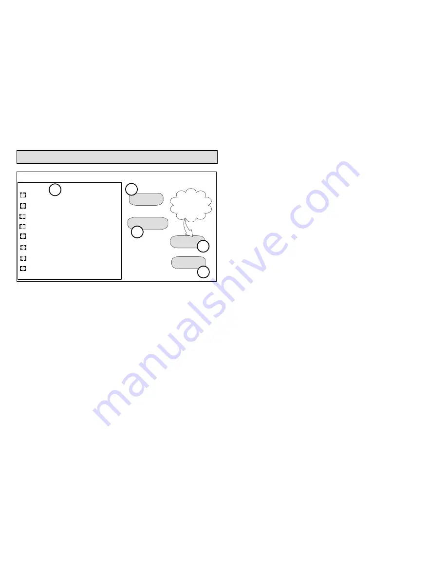
Figure 16. Selecting Tests

TO SELECT TESTS TO RUN

Use the following procedure to run tests for various
heating and cooling stage operations.
1.

Select a specific test (

1

) to run or use the 

select all

(

2

) button to run all configurations. Use the 

deselect

all

 (

3

) button to un-check desired test.

2.

Touch the 

start 

button (

4

) to run all selected tests or

touch 

skip tests

 (

5

) to end the test procedure.

3.

After the tests are completed or you have selected
skip test select the exit button to end.

NOTE - Test mode lasts for 30 minutes (with the
temperature updating every 30 seconds) except for the
defrost test, which lasts 30 seconds. Tests feature
provides the technician time to manually verify the
equipment operation.

The 

tests

 feature is available after

 set up

 has been

completed once. After you touch 

next 

in the final 

set up

screen, the “select tests to run” screen (figure 16) will
appear. (If you want you may skip tests; touch

 skip

tests

.)

To run all of the tests, touch 

select all

. All boxes in the list

of tests will be checked. Or, touch box(es) next to test(s)
to run certain tests.

After the tests have been started, the screen will
describe which test is running and show a diagnostic
summary of each test (see figure 17). After reviewing the
results and concluding that no further tests are needed,
touch 

next 

to proceed to next test. The technician must

verify that the test procedure is producing the desired
result at the equipment.

After pressing 

next

 after the final test, the 

Testing

finished

 screen will appear (figure 18). At this point, use

the 

EXIT 

button (if you have completed the required set

up), or use 

diagnostics 

button (to analyze the system),

or use 

equipment 

button (if you wish to make any

changes to device details).

Содержание 11U61

Страница 1: ...damage personal injury or loss of life Installationand service must be performed by a licensed professional HVAC installer or equivalent or service agency INSTALLER S SYSTEM SETUP GUIDE iComfort Wi Fi Flex TouchscreenProgrammable Thermostat 11U61 CONTROLS Shipping and Packing List Thermostat container includes 1 Thermostat 4 Wall anchors 1 Homeowner s manual 4 Mounting screws Equipment Interface c...

Страница 2: ...atures The iComfort Wi Fi Flex Thermostat is a 24VAC color display touchscreen and 7 day programmable thermostat It stores system parameters and settings in non volatile memory i e it retains data when electrical power fails or is turned off The iComfort Wi Fi Flex thermostat can connect to online services via the Internet through the homeowner s Wi Fi access point After online registration is com...

Страница 3: ... with time based notification of consumables including media filters UVC bulbs humidifier pads and PureAir system catalyst service replacement Humidification measurement and control Dew point adjustment control Equipment maintenance reminders Autochangeover mode Permits control of heating cooling humidification and dehumidification without user involvement Installation and Setup During initial the...

Страница 4: ...next screen CIRCULATE FAN ON TIME SETTING Circulate is enabled on the user s home screen or system settings page It keeps air circulating from 15 to 50 percent of time The following settings approximate how long the fan will run at these typical settings 15 9 minutes fan run time per hour 25 15 minutes fan run time per hour 35 21 minutes fan run time per hour 45 27 minutes fan run time per hour NO...

Страница 5: ...there is a problem no yes WARNING The dealer number is your Lennox account number i e A12345 Your dealer phone number should be the main office phone number associated with your dealership If you have any questions please contact your Lennox representative Are you sure you want to proceed Figure 3 Dealer Number Warning The following table lists all of the installer configurable system level parame...

Страница 6: ...he cause of any alerts prior to continuing set up Secure Connection Recommended Verify the home Wi Fi router supports at least one of the supports wireless bands 802 11b g or n Check router utility program or contact service provider for assistance ENABLING WI FI To enable the Wi Fi feature to communicate with a wireless router 1 Press and release Wi Fi in the lower left corner of the HOME screen ...

Страница 7: ...tatus Press to see connection status Figure 6 Enable Wi FI Open connection which which requires no password Secure connection which requires Wi Fi password security key Add a network is required when Wi Fi identification SSID is being hidden not broadcasting You will need to know the Wi Fi network name SSID security encryption type if enabled and security password if security encryption is enabled...

Страница 8: ...add new network icon to continue Enter the network name SSID If security encryption is enabled then press the security is none icon Select either WEP WPA or WPA2 2 Using the on screen keyboard enter the password security key If the network name or security key combination is incorrect or incorrectly type and access to the specified network failed a message will alert you to retry 3 If connection i...

Страница 9: ...t and server were successful Troubleshooting Wi Fi Connection ROUTER MODEM CHECK IF CONNECTION FAILS 1 Make sure the router and modem are turned on 2 Check for connections to other wireless devices and internet connection 3 Make sure the thermostat s Wi Fi is enabled and connected to the home network Router 4 If having difficulty connecting to the router online research the router model number and...

Страница 10: ...go to Wireless Settings and select a different channel Save settings B Devices cannot change Wi Fi channel It is set only at the router C On the thermostat disable then re enable the Wi Fi connection 9 Antenna in thermostat is fixed and cannot be moved Location of your access point with respect to the thermostat is very important 10 Baby monitors garage door openers and wireless video cameras may ...

Страница 11: ... to your router you can check your signal strength by pushing the Wi Fi icon on the home screen then the networks button then your network button then the router info button see figure 10 A strong wireless signal RSSI is indicated by a NEGATIVE decibel number in the range from 46 to 58db anything greater than 70db will not connect If you are connected but have a signal above 70db then you may cons...

Страница 12: ...ote access and online weather information System Desc 3 A pop up screen will appear asking if the email address below is correct Verify the email address is correct and press yes 4 Another pop up screen will appear notifying the user to check their email An email has been sent to xxxxxxxxxx lennoxind com with instructions on how to register your thermostat If you haven t received the email please ...

Страница 13: ...operations This auto update feature can be disabled by pressing the firmware update button to toggle to OFF but is not recommended NOTE Firmware updates will not affect installer or user thermostat settings Both will be retained after the update WI FI SETTINGS connected Wi Fi enabled thermostat registered Connection to server has not bee established or it has been lost Please wait until a connecti...

Страница 14: ...t will appear Fill in the User Name and Password fields and check the agree to terms and conditions box Click Create User button A series of pages and prompts follows to provide guidance through profile set up and user preference definitions USER NAME REQUIREMENT The following are the minimum user name requirements User name must begin with a letter User name has a minimum of four and a maximum of...

Страница 15: ...perature may be observed after restart This is normal operation of the thermostat while the temperature sensor algorithms adjust after a restart of the system Adding Outdoor Unit and Accessories OUTDOOR UNIT AIR CONDITIONER OR HEAT PUMP To add or remove an outdoor unit you must be at the Add or Remove Non communicating equipment screen 1 Touch the yes button next to Add or Remove Non communicating...

Страница 16: ...p procedure First the device must be installed and wired After the humidifier is installed the setting under the System mode Humidification Control Mode defaults to Basic Second if you want another mode i e Precision Basic Dew Point or Precision Dew Point the device requires further configuration see page 17 AUXILIARY DEHUMIDIFIER Before adding a dehumidifier be sure that the dehumidifier is wired...

Страница 17: ...trol Mode Touch edit 3 Touch one of the radio buttons to select the mode of humidification control touch save After saving check that the current value now shows the new selection 4 Touch the back button to return to Adjust a setting screen NOTE If the defaults for the settings are shown in red you are not required to make any changes but you must go into the edit tool and touch save When all red ...

Страница 18: ...om the Features screen select system settings 3 Touch the button of the humidification settings you want to adjust if it says humidifier OFF one touch will display a selection for ON 4 When you touch the set to button the arrows appear allowing you to change to the desired humidity percentage setting DEHUMIDIFICATION SETTINGS SYSTEM DEVICES SCREEN Pre adjustment REQUIREMENTS First the device has b...

Страница 19: ...idification if off In MEDIUM mode dehumidification occurs if these conditions are met and signals are present at specific terminals dehumidification has been enabled on installer settings and the unit is in COOL mode and dehumidification demand exists RH above setpoint and cooling demand exists Y1 energized In HIGH mode dehumidification occurs if all BASIC conditions are true except cooling demand...

Страница 20: ... 30 seconds Tests feature provides the technician time to manually verify the equipment operation The tests feature is available after set up has been completed once After you touch next in the final set up screen the select tests to run screen figure 16 will appear If you want you may skip tests touch skip tests To run all of the tests touch select all All boxes in the list of tests will be check...

Страница 21: ...rocess which begins on page 3 NOTE Compatible device found screen shown below appears only when a device has been removed and replaced with a compatible device Missing Device Equipment Type No Model No control model no Serial No control serial no Found Compatible Device Equipment Type No Model No control model no Serial No control serial no Settings were not copied iComfort Equipment Interface Mod...

Страница 22: ... changes or not but press save either way The red settings will go away after pressing save When all CFM settings are complete press the back button Press next step to advance to the tests button 8 Test the system operation and confirm the heat pump unit is electrically energized and operational Press done 9 Exit the installer set up mode by selecting the EXIT button TIPS High and Low Balance poin...

Страница 23: ... nuvango com Go to Shop All Products and scroll down to EVERYTHING ELSE and select LENNOX ICOMFORT After ordering the skin the company will email the image file jpg to you The frame skin will be mailed to you as well The skin image can be uploaded to the iComfort Wi Fi thermostat from the consumer portal site www myicomfort com under the tab skins Screen Saver You can also customize the screen sav...

Страница 24: ...eed to set up equipment parameters and edit details of devices in the system Press diagnostics if you need to analyze the system see page 20 If any component of the HVAC system has been changed e g replacing an outdoor sensor reconfiguring the system will be required To begin reconfiguring a system after you have accessed the program from the Lennox logo previous page touch the setup button The St...

Страница 25: ...quipment parameters and edit details of devices in the system without having to re run the set up program 3 Select the equipment button to continue The system devices screen will open Use the arrows to select a device and touch edit 4 Use the arrows to highlight a setting and then touch edit 5 When finished touch back equipment parameters screen then touch next Select tests to run screen appears e...

Страница 26: ...507428 01 26 Wiring Diagrams Figure 19 Thermostat and Conventional Indoor Unit and Air Conditioner ...

Страница 27: ...7 Day Programmable iComfort Wi Fi Flex Thermostat 27 Figure 20 Thermostat and Conventional Indoor Unit and Heat Pump ...

Страница 28: ... limit ed to 1500 ft 450 m Max length between components is 300 ft 90 m Note iComfort Wi Fi Flex thermostat does not require shielded cable wiring BEST PRACTICES Keep all communication wiring as far away from house electric al wiring and large electrical appliances as possible 15 5m recommended iComfort Wi Fi Equipment Interface Module Unused wires Figure 21 Thermostat Wire Termination in Communic...

Страница 29: ...d equipment interface module Thermostat did not find an Indoor Unit Make sure there is an iComfort equip ment interface module is on the system Check R i i and C connections ohm wires and cycle power Replace equipment interface module control if there is no response 14 Critical Thermostat The thermostat found more than one thermostat more than one indoor unit or more than one out door unit on the ...

Страница 30: ... Critical Thermostat The thermostat has lost communication with the furnace air handler or outdoor unit for more than 3 minutes Indicated unit has not communicated with thermostat for more than 3 minutes Check connections Ohm wires If fault persists then cycle power Fault clears after communication is restored 32 Moderate Thermostat The furnace air handler or outdoor unit is resetting itself Indic...

Страница 31: ... cleared 38 Critical Thermostat The system has not been able to turn on the heating for more than 45 minutes The system will go offline for 60 minutes and try again Run the system in diagnostic mode and verify that it matches actual equipment operation Check for other alarms codes that may be preventing the system from operating as expected Step 1 Check all heating equipment to determine cause Ste...

Страница 32: ...curs replace the control System reset is re quired to recover 180 Critical Furnace Air Handler Outdoor Unit Equipment Interface Module The thermostat has found a problem with the furnace air handler or outdoor unit outdoor sensor In normal operation after control recognizes sensors the alarm will be sent if valid temperature reading is lost Compare outdoor sensor resistance to tem perature resista...

Страница 33: ...rface Module Inter lock relay failure IFC or AHC mode only Interlock relay is energized but input is not sensed after 3 seconds There will be no heating or cooling due to this error De energize interlock relay and ener gize after 5 minutes if demand is still present 381 Moderate Critical Equipment Interface Module Inter lock relay stuck IFC or AHC modes only Interlock relay continuously sensed wit...

Страница 34: ...ng prop erly Recalibrate thermostat to clear Replace thermostat if needed 701 Moderate Thermostat The thermostat is read ing indoor temperatures above the pre programmed limit Recalibrate thermostat to clear cool thermostat adjust setpoint Replace ther mostat if needed 702 Moderate Thermostat The thermostat is read ing indoor temperatures below the pre programmed limit Recalibrate thermostat to cl...

Страница 35: ...T CODES Number Value Number Value Number Value Number Value Number Value 3000 Filter 1 3002 Humidifier Pad 3004 Maintenance 4000 User Wi Fi state change disable 4002 Image file down load failed 3001 Filter 2 3003 UV Light 3005 PureAir Main tenance 4001 Firmware download failed ...

Отзывы: