background image

A - 74 

A


LW 320 E MC / LW 400 E MC 
Version: 16.03.2015 

M A I N T E N A N C E   R E C O R D S  

Replaced Parts 

Designation 

Part number 

Date, signature 


Содержание LW 320 E MC

Страница 1: ...s if equipped Attachment A B C D E Manufacturer in terms of 97 23 EC The full name and address of the manufacturer is Lenhardt Wagner GmbH An der Tuchbleiche 39 68623 H ttenfeld Germany Phone 49 0 62...

Страница 2: ...nvoice Should verifiably defective parts have been delivered we will decide to either replace the parts or repair them The resulting transport and assembly costs will be invoiced No reduction of the p...

Страница 3: ...A Operating Instructions Breathing Air Compressor LW 320 E MC LW 400 E MC Version 03 15 E...

Страница 4: ...Transportation instructions Safety regulations 16 Installation Installation in closed rooms 18 Dimensions 19 Minimum distances 20 Ventilation 21 Electrical Installation 22 23 Operation Important opera...

Страница 5: ...cartridge change 56 Cylinder heads and valves 57 Fan protection cover dismantling Mounting the fan protection cover 58 Replace inlet and outlet valve 1st stage 59 60 Replace inlet and outlet valve 2n...

Страница 6: ...om these instructions is excluded from warranty and liability for this product Carry out other commissioning steps only if you have fully understood the following contents Before commissioning and usi...

Страница 7: ...tage pressure gauges Oil pressure monitoring c w auto shut down Cylinder head temperature monitoring with auto shut down Puracon filter monitoring Auto shut down also available Phase monitoring c w sh...

Страница 8: ...Medium Compressed Air Breathing Air Intake Pressure atmospheric Oil Pressure bar 2 5 to 4 0 5 2 5 to 4 0 5 Oil Capacity l Approx 2 Approx 2 Intake Temperature C 0 45 0 45 Ambient Temperature C 5 45 5...

Страница 9: ...W 320 E MC LW 400 E MC Version 16 03 2015 Unit Assembly D E S C R I P T I O N No Designation 1 Control Box 2 Filling Hose 3 Carrying Handle 4 Final Pressure Gauge 5 Filter Housing 6 Filling Valve 2 3...

Страница 10: ...W 320 E MC LW 400 E MC Version 16 03 2015 Switchboard D E S C R I P T I O N 1 2 3 4 5 No Designation 1 Emergency shut off switch 2 Hour counter 3 ON button 4 OFF button 5 Drain test button Option Auto...

Страница 11: ...ease Hose 9 Condensate Release Valve 10 Oil Water Separator 11 3rd Pressure Stage 12 Endpressure Safety Valve 13 Cooling Pipe Final Stage 14 Condensate Release Hose 15 Condensate Release Valve 16 Oil...

Страница 12: ...A S A F E T Y P R E C A U T I O N S...

Страница 13: ...he instruction manual is complied with and inspection and maintenance requirements are enforced No change and modification to the unit can be made without the written agreement of the manufacturer The...

Страница 14: ...Safety instructions on the unit Importance of notes and warning signs that are affixed to the compressor according to the application or its equipment S A F E T Y P R E C A U T I O N S Warning High v...

Страница 15: ...this product Comply with all local and national rules and regulations associated with this product Only trained and competent personnel are permitted to inspect repair and service the product Only au...

Страница 16: ...nsure that the machine is only taken into operation under safe and functional conditions Only operate the compressor if all protective and safety equipment e g detachable protective equipment are prov...

Страница 17: ...ay a warning sign on the main switch The machine and especially the connections and fittings should be cleaned from oil fuel and maintenance products at the beginning of the maintenance repair Do not...

Страница 18: ...er Do not stand or work under suspended loads Also separate from minor relocation machinery system of any external energy supply Before recommissioning reconnect the machine to the mains according to...

Страница 19: ...A I N S TA L L AT I O N...

Страница 20: ...such a manner that the compressor fan can intake fresh air from outside Ensure adequate ventilation and exhaust air opening When locating the compressor in rooms of less than 30 m space where natural...

Страница 21: ...A 19 A LW 320 E MC LW 400 E MC Version 16 03 2015 I N S T A L L A T I O N Dimensions Fig Dimensions...

Страница 22: ...fresh air available To prevent serious damage ensure that the cooling air flow can flow freely The following minimum distances must be adhered Front side min 1500 mm sides min 500 mm rear side min 500...

Страница 23: ...oling air flow can flow freely The necessary cooling air flow can be calculated by using the following formula 300 x drive power kW required cooling air flow m h Example 11kW motor 300 x 11kW 3300 m h...

Страница 24: ...e on the compressor The fusing should be done in accordance with the valid regulations of the responsible electricity supply company When connecting the unit to the electrical supply check the compres...

Страница 25: ...on to the switch box Recommended fuses for 360 500 V operating voltage Nominal motor power Fusing start A Connection in mm kw A Direct Star Delta Contactor supply Motor S D 5 5 11 3 25 20 2 5 1 5 7 5...

Страница 26: ...A O P E R AT I O N...

Страница 27: ...O P E R A T I O N Important operation instructions Note Ensure that all persons handling the compressor are familiar with function and operation of the unit i Wear hearing protection When working on...

Страница 28: ...ges If the turning direction is wrong immediately stop the compressor by pushing the OFF button and contact an authorised electrician 3 Check oil pressure if oil pressure gauge is installed 4 Run the...

Страница 29: ...oil level Risk of accidental loss destruction or deterioration Check V belt tension The V belts could lose tension during transportation Please check the V belt tension before starting the compressor...

Страница 30: ...the direction of rotation is wrong the guide pistons of the 2nd and 3rd stages can not be sufficiently lubricated with the consequence that the pistons will be damaged Furthermore cooling air flow wil...

Страница 31: ...O M M I S S I O N I N G Prior to daily operation observe the following Ensure cooling air can flow freely Check compressor oil level by usig the oil dipstick Check if filter cartridge is in place obs...

Страница 32: ...unit must also be started manually i 1 Close all filling valves 2 Connect the closed compressed air cylinders 3 Open cylinder valves 4 Start the compressor by pushing the ON button 5 When filling pre...

Страница 33: ...as standard with an auto shut down The unit must always be stopped manually when final pressure is reached During filling process the system can be shut down at any time by pushing the red button OFF...

Страница 34: ...A R E M E D Y I N G FA U LT S...

Страница 35: ...e leaky Replace Pipes heat exchanger broken Replace Condensate drain valves leaky Unscrew valves check sealing surfaces clean replace if necessary Final pressure switch stop unit Verify settings repla...

Страница 36: ...meter Wrong compressor rotation direction Ensure correct phase rotation observe rotation direction arrow Inlet and outlet valves contaminated defective Clean replace if necessary Safety valve leaks Ca...

Страница 37: ...dy Pressure stages are not as prescribed control pressure of pneumatic condensate valve too low Check corresponding inlet and outlet valve replace if necessary Piston sealing of pneumatic condensate v...

Страница 38: ...rtridge already partly saturated before change Store filter cartridges properly dispose defective cartridges Cylinder s piston s or piston ring s defective Replace Operating temperature too high Ensur...

Страница 39: ...A M A I N T E N A N C E A N D S E R V I C E...

Страница 40: ...y be carried out by trained personnel This is necessary because all maintenance work can not be explained exactly and detailed in this manual Only use authentic spare parts for service work Danger Com...

Страница 41: ...months or as required Maintenance work Type Quantity Order No Check Retorque all connections and bolts Check automatic condensate drain open manual condensate taps Annually Maintenance work Type Quan...

Страница 42: ...0 operating hours Maintenance work Type Quantity Order No Check Change intake filter 1 000170 Check pressure maintaining non return valve Check V belt tension and condition Note All stated quantities...

Страница 43: ...er 2nd stage 1 002123 Replace o rings of water separators after 2nd stage 1 001255 Replace o rings of the final filter housing 1 001769 Replace o ring of the DIN filling connector 1 001237 Replace o r...

Страница 44: ...1 007945 Lower gasket 2nd 1 007901 Upper gasket 3rd 1 000541 Lower gasket 3rd 1 000531 Note All stated quantities are parts of our 2000h and 4000h service kits You can find an overview on page Service...

Страница 45: ...Filter Inlet Filter V Belts Silencers In Outlet Valve Valve Seals and Compressor oil Fig Service Kits Compressor Frequency Operating Hours Order No LW 320 E MC 50 Hz 1000 h 008719 LW 320 E MC 50 Hz 2...

Страница 46: ...Use the tensioning screw to move the electric motor until the V belt tension is sufficient Then tighten mounting nuts and check V belt tension We recommend using a V belt tension gauge Correct V belt...

Страница 47: ...ted by spray oil In addition the guide cylinders of the 2nd and 3rd stage are lubricated by a mechanical oil pump The installed oil filter ensures clean oil supply to the mentioned guide cylinders Low...

Страница 48: ...oil dipstick back into its tube and screw it until stop Unscrew oil dipstick again The oil level should be between the min and max marking A max oil level is recommended If there is too much oil insid...

Страница 49: ...out oil dipstick Fill oil by using a funnel Check oil level Check o ring of the oil dipstick Insert oil dipstick The oil change is now completed Maintenance intervals First oil change after 25 operati...

Страница 50: ...Soak the gaskets with oil before placing respect mounting direction Be sure to position the arrow from the new oil sieve opposite to inlet and return ports of the pump see Fig 2 Remount the cover wit...

Страница 51: ...ilter element Fig 3 Change gasket Fig 4 Clean oil filter housing Insert filter element Fig 3 Place spring Place filter cover Fig 2 and washers Fix and tighten mounting nuts of the filter cover Fig 1 T...

Страница 52: ...housing Fig 2 Open valve spindle max 1 5 turns anti clockwise The condensate will be drained Then close valve spindle clockwise Maintenance intervals We recommend to clean oil and water separators ev...

Страница 53: ...der Remove sinter filter holder Fig 2 Change sinter filter Fig 3 screw in new sinter filter by using a suitable screwdriver Change o ring previously grease new o ring Fig 4 Place sinter filter holder...

Страница 54: ...filter cartridges are factory vacuum sealed We recommend unpacking the filter cartridges just before installation Filter cartridges which are exposed too long could be saturated with moisture and bec...

Страница 55: ...opened when it is still under pressure After opening the housing pull out the filter cartridge by the catch Fig 2 Open the packaging of the new filter cartridge and place it into the filter housing pr...

Страница 56: ...e is now completed Fig 1 Loosen filter housing topcap by using the filter tool Note Ensure that the old filter cartridge is disposed correctly at an approved waste point i Caution Do not run the compr...

Страница 57: ...maintenance Filter housing maintenance as follows Unscrew filter housing cover by using the filter tool Fig 1 Change o ring previously grease new o ring Fig 2 Screw the filter housing cover in by usin...

Страница 58: ...d be replaced every 500 working hours depending on pollution grade Inlet filter cartridge change Inlet filter cartridge change as follows Loosen cover by pushing the three clips apart Remove inlet fil...

Страница 59: ...mount valve heads to change valves The three valves are combined inlet and outlet valves The first stage is a plate valve The stages two and three are made of a spring operated piston which acts insid...

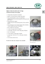
Страница 60: ...n protection cover The fan protection cover dismantling is now completed Mounting the fan protection cover Mount the fan protection cover as follows Place the fan protection cover Note the fixing stud...

Страница 61: ...g 3 Remove 1st cooling pipe Loosen pipe connections of 2nd cooling pipe Fig 4 Remove cooling pipe bracket Fig 5 Remove complete 2nd cooling pipe Remove special hexagon bolt Fig 6 Remove cylinder head...

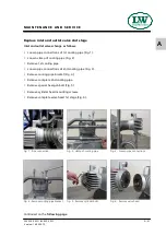
Страница 62: ...f the valve head Fig 3 Place mounting screws and special hexagon bolts and tighten crosswise tightening torque 30 Nm Fig 4 Place complete 2nd cooling pipe Connect cooling pipe braket and tighten Conne...

Страница 63: ...g 2 Remove 1st cooling pipe Loosen pipe connections of 2nd cooling pipe Fig 3 Remove cooling pipe bracket Fig 4 Remove complete 2nd cooling pipe Remove special hexagon bolt Fig 5 Remove cylinder head...

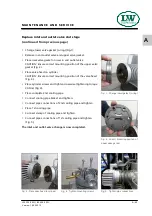
Страница 64: ...e correct mounting position of the valve head Fig 3 Place cylinder screws and tighten crosswise tightening torque 30 Nm Fig 4 Place complete 2nd cooling pipe Connect cooling pipe braket and tighten Co...

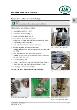
Страница 65: ...valve CAUTION Ensure correct mounting position of the upper valve gasket Fig 5 Insert new inlet and outlet valve into valve head CAUTION Observe correct position between valve centre hole and valve he...

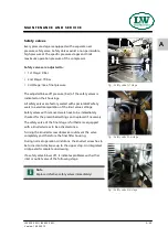
Страница 66: ...avoid manipulation of the limit value settings Safety valves with removed seals have to be immediately checked for the prescribed settings and replaced if necessary The safety valve of the final stag...

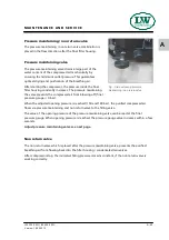
Страница 67: ...compressed air from blowing off final pressure gauge 0 bar When the adjusted opening pressure is reached 150 and 180 bar the purified compressed air flows via pressure maintaining and non return valv...

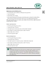
Страница 68: ...ing screw clockwise by using a suitable slotted screwdriver Start compressor and check opening pressure adjust if necessary Tighten clamp screw on the side Check opening pressure again Reduce opening...

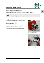
Страница 69: ...and change if necessary O ring at the filling valve Change o ring previously grease new o ring Fig 1 O ring at the filling hose Remove filling hose from the filling valve Fig 2 Change o ring previousl...

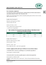
Страница 70: ...m operating pressure 350 bar Content volume 1 7 litres 350 bar x 1 7 litres 595 595 is smaller than 1000 result Test is applicable Pressure equipment from 200 up to 1000 have to be tested as follows 1...

Страница 71: ...A M A I N T E N A N C E R E C O R D S...

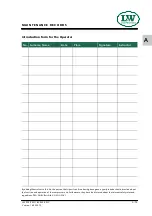
Страница 72: ...name Name Date Place Signature Instructor By adding themselves to this list the person that signs it confirms having been given a yearly introduction instruction about the function and operation of th...

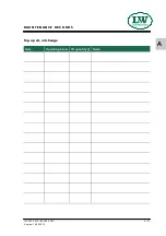
Страница 73: ...A 71 A LW 320 E MC LW 400 E MC Version 16 03 2015 M A I N T E N A N C E R E C O R D S Top up oil oil change Date Operating hours Oil quantity l Name...

Страница 74: ...A 72 A LW 320 E MC LW 400 E MC Version 16 03 2015 M A I N T E N A N C E R E C O R D S Cartridge change Date Operating hours Difference Name...

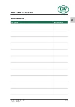
Страница 75: ...A 73 A LW 320 E MC LW 400 E MC Version 16 03 2015 M A I N T E N A N C E R E C O R D S Maintenance work Description Date signature...

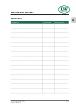
Страница 76: ...A 74 A LW 320 E MC LW 400 E MC Version 16 03 2015 M A I N T E N A N C E R E C O R D S Replaced Parts Designation Part number Date signature...

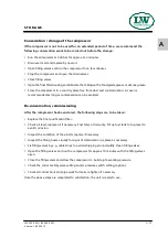
Страница 77: ...avoided De conservation commissioning After the compressor has been stored the following steps are to be taken Replace the final purification filter Check oil level replace oil if necessary Fuel Driv...

Страница 78: ...n recommissioning proceed according to the operating instructions Disposal The product must be disposed in accordance with national waste disposal regulations and by an appropriate waste disposal comp...

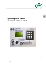
Страница 79: ...B Operating Instructions ECC Electronic compressor control www uebler net Version 11 12 E...

Страница 80: ...y II M270 9 Settings Menu M300 10 Set Stop Pressure automatic mode M320 11 Set Restart Pressure automatic mode M330 11 Set Stop Pressure semi automatic mode M340 11 Test Menu M400 12 Test Solenoids M4...

Страница 81: ...ructions is excluded from warranty and liability for this product Carry out other commissioning steps only if you have fully understood the following contents Before commissioning and using the unit c...

Страница 82: ...s automatically displayed Required service part numbers automatically displayed Fully adjustable pressure ranges for start and stop Warning messages Housing Open Emergency Switch Check of end pressure...

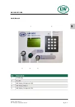
Страница 83: ...c compressor control Page B 5 B D E S C R I P T I O N Switchboard No Description 1 LCD Display 2 Key Pad 3 LED Display Compressor OFF 4 LED Display Power 5 LED Display Compressor ON 1 2 5 4 3 Version...

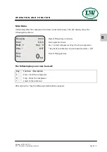
Страница 84: ...Starts the compressor 0 Stop Stops the compressor Leads to the submenus Charging 0 min Total 0 0 h Start 1 Stop 0 Help OFF Final Press 0bar The following keys can now be used After typing the key the...

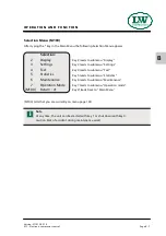
Страница 85: ...ngs Key 3 leads to submenu Settings 4 Test Key 4 leads to submenu Test 5 Statistics Key 5 leads to submenu Statistics 6 Maintenance Key 6 leads to submenu Maintenance 7 Operation Mode Key 7 leads to s...

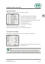
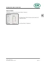
Страница 86: ...perature of the final stage cylinder head 6 Oil Temp Key 6 shows the oil temperature 7 Display II Key 7 shows Display II M200 Return Key leads back to Main Menu Charging 0 min Total 0 0 h Start 1 Stop...

Страница 87: ...e Selection Menu leads to Menu Display II Press Temp 4 0 C 0 5 0 D 0 6 0 E 0 7 0 F 0 bar C Display II M270 Return Key leads back to Main Menu This display shows further customer specific pressure and...

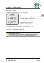
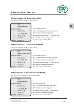
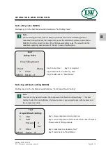
Страница 88: ...Stop Pressure 9 Close Key 9 leads back to submenu Selection M300 Return Key leads back to Main Menu Use menu M700 to change between Automatic and Semi Automatic mode Restart pressure can only be set...

Страница 89: ...Current restart pressure 7 New Value Key 7 if restart pressure should be changed XXX bar XXX indicates modified restart pressure 4 030 310 Chooseable pressure range for restart pressure 8 Confirm Key...

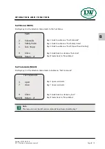
Страница 90: ...hout Venting 9 Close Key 9 leads back to submenu Selection M400 Return Key leads back to Main Menu Test Solenoids M420 Pushing key 2 in the Selection Menu leads to Submenu Test Solenoids 3 open Key 3...

Страница 91: ...ssure safety valve This would limit the maximum operating over pressure of the unit in case of malfunction i Test stop without venting M440 Pushing key 4 in the Test Menu leads to Menu Test Stop witho...

Страница 92: ...of compressor starts Maximum working pressure of unit set by safety valve test 9 Close Key 9 leads back to submenu Selection M500 Return Key leads back to Main Menu Max Press 000 bar Push key 5 to ge...

Страница 93: ...e Key 9 leads back to submenu Selection M600 Return Key leads back to Main Menu 9 Close Remaining hours depend on the type At the end of any remaining hours the display indicates a warning message Fur...

Страница 94: ...ilencer 5 Valves Key 5 receipts change of valves 6 Oil filter Key 6 receipts oil filter M680 Return Key leads back to Main Menu Maintenance Confirm Maintenance 9 Close Key 9 leads back to submenu Hour...

Страница 95: ...Key 2 activates automatic mode 3 Semi Automatic Key 3 activates semi automatic mode 4 bar mpa Key 4 selects between bar and MPa optional 5 Sprache Key 5 leads to the Language Menu 9 Close Key 9 leads...

Страница 96: ...lay can be adjusted with an adjusting screw on the back of the control Software Update Software updates can only be carried out by L W To carry out an update the device has to be send to the L W servi...

Страница 97: ...r 0 400 bar 003501 Zylinderkopf Temperatursensor Cylinderhead temperature sensor 006912 ltemperatursensor Oil temperature sensor 004840 ldruckaufnehmer 0 6 bar Oil pressure sensor 0 6 bar 006890 Druck...

Страница 98: ...et Manufacturer in terms of 97 23 EC The full name and address of the manufacturer is Lenhardt Wagner GmbH An der Tuchbleiche 39 68623 H ttenfeld Germany Phone 49 0 62 56 85 88 0 0 Fax 49 0 62 56 85 8...

Страница 99: ...C ERSATZTEILLISTEN SPARE PARTS LISTS DETAILANSICHTEN DETAILED VIEWS...

Страница 100: ...e Piston 1st Stage 28 Kompressionskolben 2 Stufe Compression Piston 2nd Stage 30 Kompressionskolben 3 Stufe Compression Piston 3rd Stage 32 Saug Druckventil 1 2 Stufe In Outlet Valve 1st 2nd Stage 34...

Страница 101: ...Inhaltsverzeichnis Table of Contents Sicherheitsventil Safety Valve 60...

Страница 102: ...C Version 03 02 2015 D E T A I L A N S I C H T D E T A I L E D V I E W Gesamtansicht Kompressor Overall View Compressor C 3 LW 320 400 E MC...

Страница 103: ...C Version 03 02 2015 D E T A I L A N S I C H T D E T A I L E D V I E W Gesamtansicht Verdichtereinheit Overall View Compressor Assembly C 4 LW 320 400 E MC...

Страница 104: ...008000 Gewindeklotz Rohrb gelbefestigung Threaded Block Pipe fixing 008059 Tragegriff Rahmen Carrying Handle 008133 Standfu Gummipuffer Rubber Stand 008286 Stopfen f r Rundrohr 25mm Plugs for round t...

Страница 105: ...Benennung Description 008416 Linsenflanschschraube M8x75 Lens Head Screw M8x75 008417 Linsenflanschschraube M10x25 Lens Head Screw M10x25 008418 Linsenflanschschraube M10x20 Lens Head Screw M10x25 008...

Страница 106: ...C Version 03 02 2015 D E T A I L A N S I C H T D E T A I L E D V I E W Baugruppe Grundgestell Assembly Main Frame C 7 LW 320 400 E MC...

Страница 107: ...C Version 03 02 2015 D E T A I L A N S I C H T D E T A I L E D V I E W Baugruppe Grundgestell Assembly Main Frame C 8 LW 320 400 E MC...

Страница 108: ...Rotation Sticker Rotation LW 250 E 008396 Gummit lle Ventilatorschutz Rubber Grommet 008397 Aufsteckstutzen L fterabdeckung Plug on Fan Cover 008419 Linsenflanschschraube M8x25mm Lens Head Screw M8x2...

Страница 109: ...C Version 03 02 2015 D E T A I L A N S I C H T D E T A I L E D V I E W Baugruppe L fterabdeckung Assembly Fan Guard C 10 LW 320 400 E MC...

Страница 110: ...C Version 03 02 2015 D E T A I L A N S I C H T D E T A I L E D V I E W Baugruppe L fterabdeckung Assembly Fan Guard C 11 LW 320 400 E MC...

Страница 111: ...densate test 002504 Taster kompl Farbe gr n Start Button colour green 003121 Not Aus Schalter komplett Emergency switch compl 004703 Einlegeschild ldruck Oil Pressure Label Oil Pressure 006859 Klemmra...

Страница 112: ...C Version 03 02 2015 D E T A I L A N S I C H T D E T A I L E D V I E W Baugruppe Elektroschaltkasten Assembly Electro Box C 13 LW 320 400 E MC...

Страница 113: ...iption 000663 Einbaumanometer mit Befestigungsb gel Press Gauge c w fixing strap 001176 U Scheibe A5 Washer A5 006254 F llventilhalter Filling Valve Holder 006341 Sechskant Blechschraube 5 5x13mm DIN7...

Страница 114: ...C Version 03 02 2015 D E T A I L A N S I C H T D E T A I L E D V I E W Baugruppe Quertraverse F llventil Assembly Transverse Traverse Filling Valve C 15 LW 320 400 E MC...

Страница 115: ...732 Mutter 06L Union Nut 06L 000733 Schneidring 6 mm Olive Seal SR 06 6mm 000734 Mutter 06S Nut 06S 000779 Verschlussstopfen 1 4 Plug 1 4 000783 Verschraubung Straight Connection 000785 Verschraubung...

Страница 116: ...002024 F llventil Kreuzbauweise Filling Valve cross 002812 Verschraubung Edelstahl Connection S S 003684 F llventil Kreuzbauweise Filling Valve cross 003685 F llventil Kreuzbauweise Filling Valve cros...

Страница 117: ...C Version 03 02 2015 D E T A I L A N S I C H T D E T A I L E D V I E W Baugruppe Hochdruckabgang Assembly High Pressure Outlet C 18 LW 320 400 E MC...

Страница 118: ...C Version 03 02 2015 D E T A I L A N S I C H T D E T A I L E D V I E W Baugruppe Hochdruckabgang Assembly High Pressure Outlet C 19 LW 320 400 E MC...

Страница 119: ...triebsmotor 11 kW 400 V o Riemens Drive Motor 11kW w o pulley 003175 Passfeder Motor LW 300 450 Woodruff Key motor 004291 Antriebsmotor 7 5 kW 400 V 50 60 Hz Motor 7 5kW 400V 50 60Hz 004395 Antriebsmo...

Страница 120: ...C Version 03 02 2015 D E T A I L A N S I C H T D E T A I L E D V I E W Baugruppe Motor Assembly Engine C 21 LW 320 400 E MC...

Страница 121: ...0866 Verschraubung Connection 000952 Sechskantschraube M6x20mm DIN933 Hexagon Screw M6x20mm DIN933 000960 Stiftschraube M8x20mm DIN939 Threaded Stud M8x20mm DIN939 001041 Zylinderschraube M8x25mm DIN9...

Страница 122: ...7904 Radial Wellendichtring Shaft seal 007912 Saug Druckventil 2 Stufe In Outlet Valve 2nd Stage 007913 Saug Druckventil 1 Stufe In Outlet Valve 1st Stage 007914 Kurbelgeh use Crankcase 007915 Deckel...

Страница 123: ...for oil filter 007971 Halterung Wasserabscheider 2 Stufe Bracket water separator 2 S 008239 lfilter Oil Filter Element 008344 UntereHalterung K hlrohr L fterabdeckung Lower Holder Fan Guard 008345 Obe...

Страница 124: ...C Version 03 02 2015 D E T A I L A N S I C H T D E T A I L E D V I E W Baugruppe Kompressorblock Assembly Compressor Block C 25 LW 320 400 E MC...

Страница 125: ...ng zu Kurbelwelle Distance ring crankshaft 007941 Distanzscheibe Pleuel Distance washer conrod 007942 Distanzscheibe Kurbelwelle Distance washer crankshaft 007976 Zylinderrollenlager cylindrical rolle...

Страница 126: ...C Version 03 02 2015 D E T A I L A N S I C H T D E T A I L E D V I E W Baugruppe Kurbeltrieb Assembly Crank Drive C 27 LW 320 400 E MC...

Страница 127: ...A R E P A R T L I S T Baugruppe Kolben 1 Stufe Assembly Piston 1st Stage Best Nr Order No Benennung Description 007973 Kolben inkl Kolbenringe Bolzen 1 St Piston compl 1st Stage 008799 Kolbenringe 1...

Страница 128: ...C Version 03 02 2015 D E T A I L A N S I C H T D E T A I L E D V I E W Baugruppe Kolben 1 Stufe Assembly Piston 1st Stage C 29 LW 320 400 E MC...

Страница 129: ...R T L I S T Baugruppe Kompressionskolben 2 Stufe Assembly Compression Piston 2nd Stage Best Nr Order No Benennung Description 008800 Kolbenringe 2 Stufe Satz Piston Rings 2nd Stage 008802 Kompressions...

Страница 130: ...C Version 03 02 2015 D E T A I L A N S I C H T D E T A I L E D V I E W Baugruppe Kompressionskolben 2 Stufe Assembly Compression Piston 2nd Stage C 31 LW 320 400 E MC...

Страница 131: ...R T L I S T Baugruppe Kompressionskolben 3 Stufe Assembly Compression Piston 3rd Stage Best Nr Order No Benennung Description 008801 Kolbenringe 3 Stufe Satz Piston Rings 3rd Stage 008803 Kompressions...

Страница 132: ...C Version 03 02 2015 D E T A I L A N S I C H T D E T A I L E D V I E W Baugruppe Kompressionskolben 3 Stufe Assembly Compression Piston 3rd Stage C 33 LW 320 400 E MC...

Страница 133: ...R T L I S T Baugruppe Saug Druckventil 1 2 Stufe Assembly In Outlet Valve 1st 2nd Stage Best Nr Order No Benennung Description 007912 Saug Druckventil 2 Stufe In Outlet Valve 2nd Stage 007913 Saug Dr...

Страница 134: ...C Version 03 02 2015 D E T A I L A N S I C H T D E T A I L E D V I E W Baugruppe Saug Druckventil 1 2 Stufe Assembly In Outlet Valve 1st 2nd Stage C 35 LW 320 400 E MC...

Страница 135: ...l 3 Stufe Assembly In Outlet Valve 3rd Stage Best Nr Order No Benennung Description 000531 Ven ldichtung Saug Druckven l unten Lower Valve Gasket 4th St 000541 Dichtring Dichtung Ven l 3 4 Stufe Upper...

Страница 136: ...C Version 03 02 2015 D E T A I L A N S I C H T D E T A I L E D V I E W Baugruppe Saug Druckventil 3 Stufe Assembly In Outlet Valve 3rd Stage C 37 LW 320 400 E MC...

Страница 137: ...iption 000861 Schneidring 18 mm Olive Seal 18 mm 000862 Mutter 18L Union Nut 18L 001005 Zylinderschraube M5x16mm DIN912 Allen Screw M5x16mm DIN912 001006 Zylinderschraube M5x20mm DIN912 Allen Screw M5...

Страница 138: ...C Version 03 02 2015 D E T A I L A N S I C H T D E T A I L E D V I E W Baugruppe K hler 1 Stufe Assembly Cooler 1st Stage C 39 LW 320 400 E MC...

Страница 139: ...Olive Seal 18 mm 000862 Mutter 18L Union Nut 18L 001013 Zylinderschraube DIN912 M6x45 Allen Bolt DIN912 M6x45 001156 Stoppmutter M6 Lock Nut M6 007967 K hlrohrklemme 2 Stufe Cooling Pipe Clamp 2 Stag...

Страница 140: ...C Version 03 02 2015 D E T A I L A N S I C H T D E T A I L E D V I E W Baugruppe K hler 2 Stufe Assembly Cooler 2nd Stage C 41 LW 320 400 E MC...

Страница 141: ...Zylinderschraube M6x45mm DIN912 Allen Bolt M6x45mm DIN912 001039 Zylinderschraube M8x16mm DIN912 Allen Screw M8x16mm DIN912 001156 Stoppmutter M6 Lock Nut M6 001176 U Scheibe A5 Washer A5 001181 U Sch...

Страница 142: ...C Version 03 02 2015 D E T A I L A N S I C H T D E T A I L E D V I E W Baugruppe K hler 3 Stufe Assembly Cooler 3rd Stage C 43 LW 320 400 E MC...

Страница 143: ...Screw M8x25mm DIN912 001134 Sechskant Schraube M12x35mm DIN933 Hexagon Screw M12x35mm DIN933 001181 U Scheibe A8 Washer A8 001193 Schnorr Scheibe S12 Clamp Washer S12 005122 U Scheibe Kurbelwelle Wash...

Страница 144: ...C Version 03 02 2015 D E T A I L A N S I C H T D E T A I L E D V I E W Baugruppe L fterrad Assembly Flywheel Assembly C 45 LW 320 400 E MC...

Страница 145: ...0811 Verschraubung Elbow Connection WE3 8 12L 000837 Verschlussstopfen Plug 001159 Stoppmutter Lock Nut M8 001181 U Scheibe A8 Washer A8 001255 O Ring O Ring 002123 Sinterfilter G3 8 AG 1 2 Stufe Sint...

Страница 146: ...C Version 03 02 2015 D E T A I L A N S I C H T D E T A I L E D V I E W Baugruppe Wasserabscheider Assembly Water Separator C 47 LW 320 400 E MC...

Страница 147: ...augfilter Assembly Intake Filter Best Nr Order No Benennung Description 000170 Ansaugfilterpatrone Air Intake Filter Cartridge 000171 Ansaugfiltergeh use inkl Patrone kompl Int Filter Housing c w filt...

Страница 148: ...C Version 03 02 2015 D E T A I L A N S I C H T D E T A I L E D V I E W Baugruppe Ansaugfilter Assembly Intake Filter C 49 LW 320 400 E MC...

Страница 149: ...embly Oil Drainage Tube Best Nr Order No Benennung Description 000817 Verschraubung Connection 001005 Zylinderschraube M5x16mm DIN912 Allen Screw M5x16mm DIN912 002153 lablassschlauch inkl Kugelhahn O...

Страница 150: ...C Version 03 02 2015 D E T A I L A N S I C H T D E T A I L E D V I E W Baugruppe lablassschlauch Assembly Oil Drainage Tube C 51 LW 320 400 E MC...

Страница 151: ...A6 Washer A6 000737 Verschraubung Connection 000761 Winkelverschraubung Elbow Connection 000765 Schneidring 8 mm Olive Seal 8 mm 000766 Mutter 08L Nut 08L 000958 Gewindestift M8x16mm DIN914 Hexagon S...

Страница 152: ...C Version 03 02 2015 D E T A I L A N S I C H T D E T A I L E D V I E W Baugruppe lpumpe Assembly Oil Pump C 53 LW 320 400 E MC...

Страница 153: ...ube M4x5mm DIN553 Worm Screw M4x5mm DIN553 001041 Zylinderschraube M8x25mm DIN912 Allen Screw M8x25mm DIN912 001159 Stoppmutter M8 Lock Nut M8 001181 U Scheibe A8 Washer A8 001716 Obere Verschlussschr...

Страница 154: ...se LW 320 E MC Assembly Final Filter Tower LW 320 E MC Best Nr Order No Benennung Description 003077 Entw sserungsventil G1 4 AG konisch Drain valve G1 4 male 008419 Linsenflanschschraube M8x25mm Lens...

Страница 155: ...C Version 03 02 2015 D E T A I L A N S I C H T D E T A I L E D V I E W Baugruppe Endfiltergeh use LW 320 E MC Assembly Final Filter Tower LW 320 E MC C 56 LW 320 400 E MC...

Страница 156: ...ith fixed nut 000837 Verschlussstopfen Plug 000941 Madenschraube M4x5mm DIN553 Worm Screw M4x5mm DIN553 001028 Zylinderschraube M6x25mm DIN912 Allen Bolt M6x25mm DIN912 001041 Zylinderschraube M8x25mm...

Страница 157: ...w sserungsventil G1 4 AG konisch Drain valve G1 4 male 008282 Druckbeh lterrohr 95x470mm Tube Filter Housing 95x470mm 008347 Filter Nippel mit Aufnahme 1 7L Filter Nipple 1 7ltr 008348 D senrohr Hochd...

Страница 158: ...C Version 03 02 2015 D E T A I L A N S I C H T D E T A I L E D V I E W Baugruppe Endfiltergeh use LW 400 E MC Assembly Final Filter Tower LW 400 E MC C 59 LW 320 400 E MC...

Страница 159: ...entil Bauteilgepr ft Safety Valve T V 300 bar 000556 Sicherheitsventil Bauteilgepr ft Safety Valve T V 330 bar 000557 Sicherheitsventil Bauteilgepr ft Safety Valve T V 350 bar 001058 Zylinderschraube...

Страница 160: ...C Version 03 02 2015 D E T A I L A N S I C H T D E T A I L E D V I E W Baugruppe Sicherheitsventil Assembly Safety Valve C 61 LW 320 400 E MC...

Страница 161: ...D O P T I O N S...

Страница 162: ...Condensation Drain 5 Auto Shut Down 23 Auto Start Function 27 Interstage Pressure Gauge 35 Oil Pressure Gauge 40 Oil Pressure Monitoring 43 Switch Over Device 200 300bar 48 200 300bar Parallel Fillin...

Страница 163: ...C A D D I T I O N A L F I L L I N G H O S E D 2 LW 320 400 E MC...

Страница 164: ...DIN912 001152 Stoppmutter M Lock Nut M5 001176 U Scheibe A5 Washer A5 008257 Verteilerblock 5xG1 4 Distributor Block 5xG1 4 008258 Verteilerblock 2xG1 4 Distributor Block 2xG1 4 008600 VA Rohr Hochdr...

Страница 165: ...C Version 03 02 2015 A D D I T I O N A L F I L L I N G H O S E D 4 LW 320 400 E MC...

Страница 166: ...D A U T O M A T I C C O N D E N S AT I O N D R A I N D 5 LW 320 400 E MC...

Страница 167: ...switch box and activates the dump valves about every 15 minutes To release the complete condensate through the black plastic hoses we recommend using an 10 l container at least The drain noise can be...

Страница 168: ...rify the compressor for release noises A slight hiss of the air inlet filter nozzle can be ignored If release noises occur localise blow off position s Switch off the compressor Disconnect the compres...

Страница 169: ...top Change sinter filter Fig 2 Reassemble all parts and tighten nut Change o ring previously grease new o ring Fig 3 Place separator top and tighten ring nut manually Replace silencer Mount oil water...

Страница 170: ...densate valve Loosen connection Fig 2 Change sinter filter Fig 3 Tighten horizontal screw Mount pneumatic condensate valve Tighten pipe connections and mounting screws Pneumatic condensate valve maint...

Страница 171: ...te hose 8x1mm Polyamid 008601 VA Rohr Kondensatautom labscheider Pipe 008602 VA Rohr Wasserabs 2 S Kondensatautom Pipe 008609 VA Rohr HD Filter Kondensatautomatik Pipe Overall View Automatic Condensat...

Страница 172: ...D Version 03 02 2015 Overall View Automatic Condensation Drain A U T O M A T I C C O N D E N S A T I O N D R A I N D 11 LW 320 400 E MC...

Страница 173: ...pneum Kondensatventil Piston 000196 D senschraube pneum Kondensatventil Inlet Jet Screw 000197 Stopfen pneum Kondensatventil Plug 000198 Geh use pneum Kondensatventil Body PCV 000498 U Scheibe A6 Was...

Страница 174: ...D Version 03 02 2015 Assembly Pneumatic Condensate Valve A U T O M A T I C C O N D E N S A T I O N D R A I N D 13 LW 320 400 E MC...

Страница 175: ...N D R A I N Best Nr Order No Benennung Description 000892 Doppelnippel Double Nipple 001546 Aludichtring f r Magnetventile G1 4 Alloy Seal Ring for G1 4 male 005855 Winkeleinschraubverschraubung 8 mm...

Страница 176: ...cheibe A6 Washer A6 000710 Verschraubung Connection w o nut olive seal 000921 Reduzierung Reducer 001156 Stoppmutter M6 Lock Nut M6 001159 Stoppmutter M8 Lock Nut M8 001181 U Scheibe A8 Washer A8 0012...

Страница 177: ...D Version 03 02 2015 Assembly Oil Water Separators Final Stage A U T O M A T I C C O N D E N S A T I O N D R A I N D 16 LW 320 400 E MC...

Страница 178: ...m 006356 Kondensatbeh lter 10 Liter Condensate Catch Tank 10 Litre 006379 Zugfeder Kondensatfilterpatrone Spring Condensate Filter Cartr 006460 Federspannblech Kondensatbeh lter Spring Clamping Plate...

Страница 179: ...D Version 03 02 2015 Assembly Housing Condensate Catch Tank A U T O M A T I C C O N D E N S A T I O N D R A I N D 18 LW 320 400 E MC...

Страница 180: ...I N Best Nr Order No Benennung Description 000203 Druckschalter G1 4 IG PV 50 350 bar Pressure Switch 50 350 bar 000749 Verschraubung Connec on with xed nut 000757 T Verschraubung T Connec on with xed...

Страница 181: ...D Version 03 02 2015 Assembly Final Filter Tower A U T O M A T I C C O N D E N S A T I O N D R A I N Automatic Condensation Drain Automatic Condensation Drain Auto Shut Down D 20 LW 320 400 E MC...

Страница 182: ...condensate test 002504 Taster kompl Farbe gr n Start Button colour green 003121 Not Aus Schalter komplett Emergency switch compl 004703 Einlegeschild ldruck Oil Pressure Label Oil Pressure 006859 Klem...

Страница 183: ...D Version 03 02 2015 Switch Box with Condensate Drain Test Switch A U T O M A T I C C O N D E N S A T I O N D R A I N D 22 LW 320 400 E MC...

Страница 184: ...D A U T O S H U T D O W N D 23 LW 320 400 E MC...

Страница 185: ...Increasing cut out pressure Turn the adjusting screw clockwise Reducing cut out pressure Turn the adjusting screw anti clockwise Adjust the pressure switch in steps of a quarter turn Restart the comp...

Страница 186: ...sure gauge The safety valve should open when reaching working pressure of the compressor If not switch off the unit and take out of service until the safety valve has been replaced Switch off the comp...

Страница 187: ...Best Nr Order No Benennung Description 000203 Druckschalter G1 4 IG PV 50 350 bar Pressure Switch 50 350 bar 000749 Verschraubung Connection with fixed nut 000757 T Verschraubung T Connection with fi...

Страница 188: ...D A U T O S T A R T F U N C T I O N D 27 LW 320 400 E MC...

Страница 189: ...sure decreases below the selected minimum pressure the unit automatically restarts To enable a manual start shut off automatic operation by pushing the Stop button Start button lamp goes out Now turn...

Страница 190: ...last test date are rated for the final pressure are free from humidity i 1 Turn selector switch to semi automatic mode 2 Close all filling valves 3 Connect closed compressed air cylinders 4 Open fill...

Страница 191: ...y 8 Close and vent all filling valves 9 Disconnect all compressed air cylinders from filling valves 10 If automatic operation is interrupted by pushing the OFF button turning the selector switch tripp...

Страница 192: ...e condensate test 002504 Taster kompl Farbe gr n Start Button colour green 003121 Not Aus Schalter komplett Emergency switch compl 004691 Schlie er Kontakt Front Closing contact front 004703 Einlegesc...

Страница 193: ...007013 007013 Drucktaster EIN Button ON 002504 Drucktaster AUS Button OFF 008153 Drucktaster Kondensat Test Button Drain Test 002502 LED Leuchte rot LED light red 008840 Klemmrahmen Label holder 00685...

Страница 194: ...D Version 03 02 2015 A U T O S T A R T F U N C T I O N Holder Switch box D 33 LW 320 400 E MC...

Страница 195: ...D Version 03 02 2015 A U T O S T A R T F U N C T I O N Pressure Switch 50 350 bar D 34 LW 320 400 E MC...

Страница 196: ...D I N T E R S TA G E P R E S S U R E G A U G E D 35 LW 320 400 E MC...

Страница 197: ...le pressure gauge This is serviceable for troubleshooting and allows detecting faults at an early stage Indicated interstage pressures depend on final pressure settings The pressure gauges should show...

Страница 198: ...w fixing strap 000663 Einbaumanometer mit Befestigungsb gel Press Gauge c w fixing strap 000710 Verschraubung Connection w o nut olive seal 000721 Verschraubung Connection 002507 Einbaumanometer glyz...

Страница 199: ...D Version 03 02 2015 I N T E R S T A G E P R E S S U R E G A U G E Detailed View 000660 008935 008935 002507 000663 008925 D 38 LW 320 400 E MC...

Страница 200: ...D Version 03 02 2015 I N T E R S T A G E P R E S S U R E G A U G E Detailed View 000710 008935 000721 008935 D 39 LW 320 400 E MC...

Страница 201: ...D O I L P R E S S U R E G A U G E D 40 LW 320 400 E MC...

Страница 202: ...irection see rotation direction arrow Oil level too low not enough oil in the compressor Oil pump filter contaminated Oil intake pipe damaged defective Oil temperature below 5 C lubrication not possib...

Страница 203: ...der No Benennung Description 000655 Einbaumanometer mit Befestigungsb gel Press Gauge glycerine brass 000721 Verschraubung Connection 008934 Manometerschlauch Minime schlauch Pressure Gauge Hose O I L...

Страница 204: ...D O I L P R E S S U R E M O N I T O R I N G D 43 LW 320 400 E MC...

Страница 205: ...sure of 0 5 bar The red warning lamp Oil Pressure Monitoring lights up Possible causes of fault Wrong compressor rotation direction see rotation direction arrow Oil level too low not enough oil in the...

Страница 206: ...ss 000712 Verschraubung Connection w o nut olive seal 000721 Verschraubung Connection 000732 Mutter Union Nut 06L 000733 Schneidring 6 mm Olive Seal SR 06 6mm 001021 Zylinderschraube Allen Bolt 001176...

Страница 207: ...D Version 03 02 2015 O I L P R E S S U R E M O N I T O R I N G Detailed View D 46 LW 320 400 E MC...

Страница 208: ...D Version 03 02 2015 O I L P R E S S U R E M O N I T O R I N G Detailed View D 47 LW 320 400 E MC...

Страница 209: ...C S W I T C H O V E R D E V I C E 2 0 0 3 0 0 B A R D 48 LW 320 400 E MC...

Страница 210: ...ressure selector spindle 1 should be screwed fully out anti clockwise S W I T C H O V E R D E V I C E 2 0 0 3 0 0 B A R Switch over Device Drain Valve at Final Filter Tower ATTENTION Operate 200 300ba...

Страница 211: ...O Ring D senschraube O Ring Inlet Jet 001808 Sicherheitsventil 3 Stufe 330bar Safety Valve 3rd Stage 330bar 002135 Sicherheitsventil 3 Stufe 225bar Safety Valve 3rd Stage 225bar 002136 Sicherheitsvent...

Страница 212: ...C Version 03 02 2015 S W I T C H O V E R D E V I C E 2 0 0 3 0 0 B A R Switch Over Device 200 300bar D 51 LW 320 400 E MC...

Страница 213: ...D 2 0 0 3 0 0 B A R PA R A L L E L F I L L I N G P R E S S U R E O P E R AT I O N D 52 LW 320 400 E MC...

Страница 214: ...he compressor is equipped with a pressure reducer a second final pressure safety valve and a second filling pressure gauge The handwheels or gaiters are colour coded to allow an optical differentiatio...

Страница 215: ...ung Straight Connection 000838 Verschlussstopfen Plug 001042 Zylinderschraube Allen Screw 001058 Zylinderschraube Allen Bolt 001181 U Scheibe A8 Washer A8 001244 O Ring O Ring flange safety valve 0014...

Страница 216: ...D Version 03 02 2015 200 300 BAR PARALLEL FILLING PRESSURE OPERATION Detailed View D 55 LW 320 400 E MC...

Страница 217: ...D A I R C O O L E R C O N N E C T I O N K I T D 56 LW 320 400 E MC...

Страница 218: ...ing to the connection designation inlet outlet How to connect the air cooler connection kit Connect the outlet of the air cooler adapter to the inlet of the air cooler Connect the inlet of the air coo...

Страница 219: ...ngsrohr VA 8mm Connecting Pipe Air Cooler 008951 Verbindungsrohrbogen VA 10mm Connecting Pipe Air Cooler 008952 Adapter Air Cooler Adapter Air Cooler 000738 Verschraubung Connection 000783 Verschraubu...

Страница 220: ...D Version 03 02 2015 Detailed View A I R C O O L E R C O N N E C T I O N K I T D 59 LW 320 400 E MC...

Страница 221: ...E A T T A C H M E N T Version 11 12 E...

Отзывы: