


Chapter 6: DEC-6801/DES-6801 Decoder with Frame Synchronizer Module
Operations
74
6800/7000 Series - Audio and Video Multi/Demultiplexing Products Installation and Operation Manual
Operations
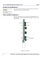
The following sections describes the controls and indicators located at
the front edge of the desirable module.
Controls
The
Selector
16-position rotary switch selects control parameters.
See
“Bank B2,” on page 78
.
•
The
Adjuster
two-position toggle switch adjusts parameter values.
•
The
Service Push
button allows you to locate the position of the
particular module in the network when one or multiple modules are
linked together over a 75
Ω
network (DigiNet) and connected to the
Central Controller
(PC or Leitch DigiNet panel).
•
The
Frequency Adjust
switch sets the free-running clock rate.
LED Indicators
•
The
Bank A/B
LED indicates the selected Bank: Bank A is selected if
the
Bank A/B
LED is
Off
(factory default), and Bank B is selected if
the
Bank A/B
LED is
On
.
•
The
625 Auto 525
LEDs indicate the standard: The
525/625
LEDs
indicate a detected standard if the
Auto
LED is
On
, and a forced line
standard if the
Auto
LED is
Off
.
•
The
Unlocked
LED indicates (when lit) that the module cannot lock
onto the incoming composite signal or that the
Incoming
signal is
not present.
•
The
Service
LED lights up for a short time at power up but remains
Off
during normal operation. If the
Service
LED is blinking or
continuously
On
, a hardware failure has been detected.
Содержание 6800/7000 Series
Страница 4: ......
Страница 22: ...Preface xx 6800 7000 Series Audio and Video Multi Demultiplexing Products Installation and Operation Manual ...
Страница 230: ......