31
_________________________________________________________________________________________
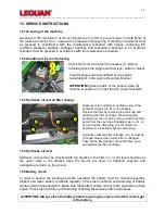
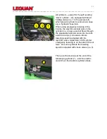
All cylinders
– except for the self levelling
”slave” cylinder – are equipped with load
holding valves (no. 1 in the picture left),
which prevent cylinder movements in case
e.g. a hydraulic hose fails.
When using emergency lowering of the
booms, the electric solenoid valve in the
cylinder (no. 2) opens and oil flows through
the adjustable restrictor valve into the tank
and the boom(s) come down. Boom
lowering speed is adjusted with the
restrictor valve. Adjustment of lift cylinder
emergency lowering is on the side of the oil
tank. On some cylinders the lowering
speed is adjusted with check valves (no. 3).
There are check valves at the end of the
telescoping cylinder (1) , and the electric
valve K7 (2) that restricts cylinder stroke.
1
2
1
3
2
1
2
3
Содержание 125
Страница 1: ...Operators and Service Manual 2014 Version 6 2015 27 8 2015 ...
Страница 9: ...9 _________________________________________________________________________________________ ...
Страница 10: ...10 _________________________________________________________________________________________ 3 1 Reach diagram ...


