30
_________________________________________________________________________________________
1
3
2
5
1
7
6
8
4
15.6 Check of set up outrigger control system
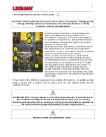
Always check the function of the set up outrigger control system when starting operation. If
the red LED indicators don’t light up, lift briefly all four outrigger control valve levers. If all red
LEDs now light up and the green indicator doesn’t, the set up system works correctly. After
this the setting of outriggers can be done as usual.
ATTENTION! If the set up control system doesn’t work correctly, contact Leguan
service. It is not allowed to use this access platform, and the failure/defect must be
repaired before starting operation.
15.7 Water level check
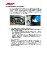
Correct position of the water level (on top of the control valve box at ground level) in relation
to the upper surface of the chassis must be checked in accordance with the maintenance
schedule, or if there is reason to believe that the position of the water level has changed:
Make sure that the booms are in transport position and put a water level on the chassis.
Compare the position of this water level to the position of the water level on the control valve
box. If the positions are different, adjust the water level on the valve box with the adjustment
screws so that both levels are in the same position. Do the adjustment both lengthwise and
sideways.
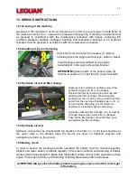
15.8 Adjustments in hydraulic system
All settings of the hydraulic system have
been made at the factory and normally
there is no need to adjust them.
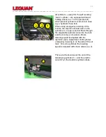
Picture left shows the valves in the valve
box at ground level. The components are:
1. Hydraulic pressure check fitting. All
hydraulic pressures are measured here.
2. Drive control valve, solenoid K98B
(outriggers)
3. Drive control valve, main pressure
adjustment 275 bar
4. Selector valve of lower controls K11S
(option, lower controls)
5. Drive control valve, solenoid K98A
(booms)
6. Tank line collector block, boom pressure
solenoid K9
7. Outrigger pressure switch PS5
8.
Outrigger pressure switches, PS1…PS4.
Pressure is adjusted with the screw in
the middle of the fitting. Adjustment 100
bar.
Main hydraulic pressure (no. 3 in picture) is adjusted from the pressure relief valve of the
drive control valve. Outrigger pressure is adjusted from the pressure relief valve of the
outrigger control valve. Boom pressures are adjusted from the boom control valve. Slewing
speed is adjusted from the check valve that is located on the side of boom control valve.
Содержание 125
Страница 1: ...Operators and Service Manual 2014 Version 6 2015 27 8 2015 ...
Страница 9: ...9 _________________________________________________________________________________________ ...
Страница 10: ...10 _________________________________________________________________________________________ 3 1 Reach diagram ...


