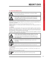
68
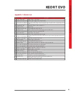
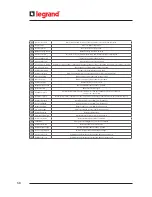
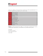
42
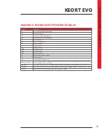
Inverter overload
RMS current drawn from any of the output lines exceeds its nominal value.
43
Bypass active
UPS is on Bypass Operation.
44
Inverter passive
Inverter does not operate now.
45
Output voltage failure
Output voltage is beyond its limits
46
Master com. lost
This alarm is observed when information flow from master ups is interrupted
47
Input voltage high
Input voltage is higher than its limit.
48
Input voltage low
Input voltage is lower than its limit.
49
Rec. not sync. with Inp.
Frequency of input voltage is beyond the frequency range for bypass operation or bypass mains voltage is very low
50
Inp. ph. seq. wrong
Phase sequence of input mains voltages is not OK.
51
Rectifier temp. high
Rectifier block temperature is very high.
52
Rectifier overload
RMS current drawn from any of the input lines exceeds its nominal value.
53
DC voltage high
DC bus voltages are higher than its upper limit.
54
DC voltage low
DC bus voltages are lower than its lower limit.
55
Rectifier passive
Rectifier does not operate now.
56
Output breaker open
Output Circuit Breaker is at “OFF” position.
57
Batt. test active
Battery test is on progress.
58
Redundancy lost
Parallel system alarm. The total load is more than the redundancy load. The formula is :
Load % > N / (N+1) * 100
59
N number failure
Parallel system alarm. If the UPS number in parallel is less than the preadjusted N number, that alarm appears.
60
Rectifier disabled
Rectifier enabled is set as “NO” from front panel.
61
Inverter disabled
Inverter enabled is set as “NO” from front panel.
62
Bypass disabled
Bypass enabled is set as “NO” from front panel.
63
Eco mode active
Eco Mode enabled is set as “YES” from front panel.
64
Batt. discharging
Battery is discharging.
65
Ambient temp. high
Ambient temperature exceeds its upper limit.
66
Gen. mode active
Generator friendly operation is activated.
67
ESD active
Emergency Switching Device interface is activated.
68
Battery test failure
Batteries failed in the battery test.
69
Battery breaker open
Battery Circuit Breaker is at “OFF” position.
70
Rec. not precharged
DC bus voltage is not equal to input voltage.
71
Inverter com. lost
Communication between the inverter and the front panel is lost.
72
Rectifier com. lost
Communication between the rectifier and the front panel is lost.
Содержание KEOR T EVO
Страница 1: ...KEOR T EVO 10 15 20 KVA Installation Operation Manual LE10507AA ...
Страница 2: ...LE10507AA KEOR T EVO ...
Страница 24: ...22 Figure 6 3 1 3 Figure 6 3 1 4 Power Cables Path Communication Cables Path ...
Страница 30: ...28 Figure 6 3 1 4 1 KEOR T EVO 10 1x24pcs 9Ah BATTERY WIRING DIAGRAM ...
Страница 31: ...29 KEOR T EVO Installation Operation Manual Figure 6 3 1 4 2 KEOR T EVO 10 1x24pcs 9Ah BATTERY WIRING DIAGRAM ...
Страница 32: ...30 Figure 6 3 1 4 3 KEOR T EVO 10 1x24pcs 9Ah BATTERY WIRING DIAGRAM ...
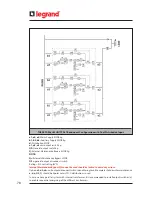
Страница 76: ...74 SEPARATED RECTIFIER AND BYPASS INPUTS FOR SINGLE UPS UNIT ...
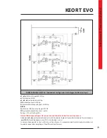
Страница 77: ...75 KEOR T EVO Installation Operation Manual COMMON RECTIFIER AND BYPASS INPUTS FOR SINGLE UPS UNIT ...
Страница 82: ...Notes ...
Страница 83: ......

