59
KEOR T EVO
Installa
tion & Oper
ation M
anual
CAUTION:
Do not remove the communication cables between the UPS’s during
parallel operation.
In case the communication cable is removed or damaged during parallel operation and the communication
is lost then the slave UPS which cannot communicate with the master UPS will disconnect from the output
bus and turn off. The other UPSs will continue normal operation. In such a case, this UPS should be turned
off completely in order to insert its communication cable again and then switched on again.
Start up for “PARALLEL” UPSs not on Maintenance Bypass Mode;
1.
Switch the auxiliary supply circuit breaker on the distribution panel to
“ON”
position.
2.
Switch the mains supply circuit breaker on the distribution panel to
“ON”
position.
3.
Switch
Q4
(Auxiliary Supply) circuit breakers of all UPSs
“ON”
position.
4.
Switch
Q1
(Mains Supply) circuit breakers of all UPSs to
“ON”
position.
5.
Switch
Q6
(Inrush) circuit breakers of all UPSs to
“ON”
position.
6.
Touch Battery icon to see
Battery / DC
menu measurement. Do not close the battery circuit breakers (F5)
until the DC bus r/- 372V.
7.
If exists, switch external Battery circuit breaker to
“ON”
position.
8.
Switch
Q2
(Output) circuit breakers of all UPSs to
“ON”
position.
9.
If exists, switch the output circuit breakers on the distribution panel to
“ON”
position (
o
unit output
switch and
OS
General Output switch).
Start up for “PARALLEL” UPSs on Maintenance Bypass Mode;
1.
Switch
Q4
(Auxiliary Supply) circuit breakers of all UPSs
“ON”
position.
2.
Switch
Q1
(Mains Supply) circuit breakers of all UPSs to
“ON”
position.
3.
Switch Q6 (Inrush) circuit breakers of all UPSs to
“ON”
position.
4.
LCDs will be
ON
. See
“M. Bypass Mode”
written on LCD of all UPS.
5.
Touch Battery icon to see
Battery / DC
menu measurement. Do not close the battery circuit breakers (F5)
until the DC bus r/- 372V.
6.
If exists, switch external Battery circuit breakers to
“ON”
position.
7.
Switch F5 (Battery) circuit breakers of all UPSs to
“ON”
position.
8.
Switch
Q2
(Output) circuit breakers of all UPSs to
“ON”
position.
9.
If exists, switch the output circuit breakers on the distribution panel to
“ON”
position (
o
unit output
switch and
OS
General output switch).
10.
Switch
Q3
(Maintenance Bypass) circuit breakers of all UPSs to
“OFF”
position.
11.
If exists, Switch Q ( External Maintenance Bypass) circuit breaker to
“OFF”
position.
12.
See
“Online Mode”
written on LCDs
10.2.
Procedure for Commissioning and Start-Up
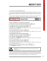
If the UPSs are not factory parallel configured; the initially started-up UPS will operate as master and
the remaining UPS’s will operate as slave. According ID numbers defined for each UPS, Master and Slave
messages should be observed on the LCD panel. On the master unit, candidate master UPS is also shown
as CX.
CX represents the best available master candidate UPS among the slave UPSs. X represents the ID number
of this slave UPS. In case the master UPS fails, then this candidate assigned UPS becomes Master.
ID-1 Master / CX Online Mode
Menu
Содержание KEOR T EVO
Страница 1: ...KEOR T EVO 10 15 20 KVA Installation Operation Manual LE10507AA ...
Страница 2: ...LE10507AA KEOR T EVO ...
Страница 24: ...22 Figure 6 3 1 3 Figure 6 3 1 4 Power Cables Path Communication Cables Path ...
Страница 30: ...28 Figure 6 3 1 4 1 KEOR T EVO 10 1x24pcs 9Ah BATTERY WIRING DIAGRAM ...
Страница 31: ...29 KEOR T EVO Installation Operation Manual Figure 6 3 1 4 2 KEOR T EVO 10 1x24pcs 9Ah BATTERY WIRING DIAGRAM ...
Страница 32: ...30 Figure 6 3 1 4 3 KEOR T EVO 10 1x24pcs 9Ah BATTERY WIRING DIAGRAM ...
Страница 76: ...74 SEPARATED RECTIFIER AND BYPASS INPUTS FOR SINGLE UPS UNIT ...
Страница 77: ...75 KEOR T EVO Installation Operation Manual COMMON RECTIFIER AND BYPASS INPUTS FOR SINGLE UPS UNIT ...
Страница 82: ...Notes ...
Страница 83: ......


