37
KEOR T EVO
Installa
tion & Oper
ation M
anual
7.1.1.
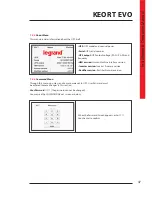
Colour Graphical Touchscreen
Energy Flow Diagram/Modes Of Operation
and
Menus
are displayed on LCD.
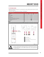
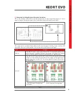
The description of the symbols in the energy flow diagram:
Bypass Input:
If Bypass voltage is OK and synchronizes with inverter; it lits Green, If Bypass voltage is
OK and not synchronizes with inverter; it lits Orange.
Rectifier Input:
If Input voltage is OK, it lits Green.
Rectifier:
Converts AC voltage at the input into DC voltage. You may reach the rectifier measurements
by touching it.
Bypass Line:
Shows that the loads are supplied via Bypass and line colour is Orange. If UPS is on Eco
Mode it is Green.
Battery:
Shows battery conditions. If it is discharging the indicator goes down, if it is charging the
indicator goes up. You may reach the battery/DC measurements by touching it.
Inverter:
Converts DC voltage into AC voltage. You may reach the output measurements by touching
it.
Operation Mode Information:
Shows UPS’s current operation mode.
Load:
Shows the percentage of the load as numerical and graphical information. If there is overload at
the output the load graphic lits Red. You may reach the output power measurements by touching it.
Menu:
You may reach the menus by touching it.
Configuration:
It indicates if UPS is in parallel or single operation configuration. In Single Mode; there
is no symbol.
Time:
It indicates the time.
Circuit Breaker:
It appears if battery Fuse is in “OFF” position or battery fuse has blown. If battery Fuse
is in “ON” position; the circuit breaker icon is not displayed, instead battery capacity percentage is
displayed.
Alarms:
If there is an alarm on UPS this icon appears and informs the user by flashing. You may reach
the alarms by touching it.
Exclamation Mark:
Indicates that there is a problem where the icon appears.
Transfer:
Indicates that transfer to bypass is disabled.
Wrench:
Indicates that UPS requires Periodic Preventive Maintenance.
Temperature:
Indicates ambient temperature of UPS is too high.
Generator Mode:
Indicates UPS operates on Generator Mode.
10
1
2
3
14
5
6
12
14
13
18
4
16
15
8
11
17
7
9
1
2
3
4
5
6
7
8
9
10
11
12
13
14
15
16
17
18
Содержание KEOR T EVO
Страница 1: ...KEOR T EVO 10 15 20 KVA Installation Operation Manual LE10507AA ...
Страница 2: ...LE10507AA KEOR T EVO ...
Страница 24: ...22 Figure 6 3 1 3 Figure 6 3 1 4 Power Cables Path Communication Cables Path ...
Страница 30: ...28 Figure 6 3 1 4 1 KEOR T EVO 10 1x24pcs 9Ah BATTERY WIRING DIAGRAM ...
Страница 31: ...29 KEOR T EVO Installation Operation Manual Figure 6 3 1 4 2 KEOR T EVO 10 1x24pcs 9Ah BATTERY WIRING DIAGRAM ...
Страница 32: ...30 Figure 6 3 1 4 3 KEOR T EVO 10 1x24pcs 9Ah BATTERY WIRING DIAGRAM ...
Страница 76: ...74 SEPARATED RECTIFIER AND BYPASS INPUTS FOR SINGLE UPS UNIT ...
Страница 77: ...75 KEOR T EVO Installation Operation Manual COMMON RECTIFIER AND BYPASS INPUTS FOR SINGLE UPS UNIT ...
Страница 82: ...Notes ...
Страница 83: ......


