7
the BFS, the main burner is extinguished (if boiler is running) or
the boiler will not start up.
BLOWER PROVER SWITCH
The Blower Prover Switch (BPS) fig. 4, is similar in construction
to the BFS. It is a single-pole, normally open pressure switch
that will close its contacts when a rising positive pressure of
1.0 in. w.c. (0.25 kPa) is encountered. The contacts will open
when the pressure falls below the fixed set point of 1.0 in. w.c.
(0.25 kPa) The BPS monitors the pressure inside the blower
elbow. If the blower is not operating at a sufficient blowing capacity,
the main burner is extinguished (if boiler is running) or the boiler
will not start up.
LOW GAS SWITCH
The Low Gas Switch (LGS) fig. 5, is a single-pole, normally open
pressure switch that will close its contacts when a rising pressure
of 5.0 in. w.c. (1.24 kPa) is encountered. The contacts will open
when the pressure falls below the fixed set point of 5.0 in. w.c.
(1.24 kPa) The LGS monitors the gas supply pressure to the
boiler. If the gas supply falls below 5.0 in. w.c. (1.24 kPa), the
main burner is extinguished (if boiler is running) or the boiler will
not start up.
FIGURE 5. LOW GAS SWITCH (LGS)
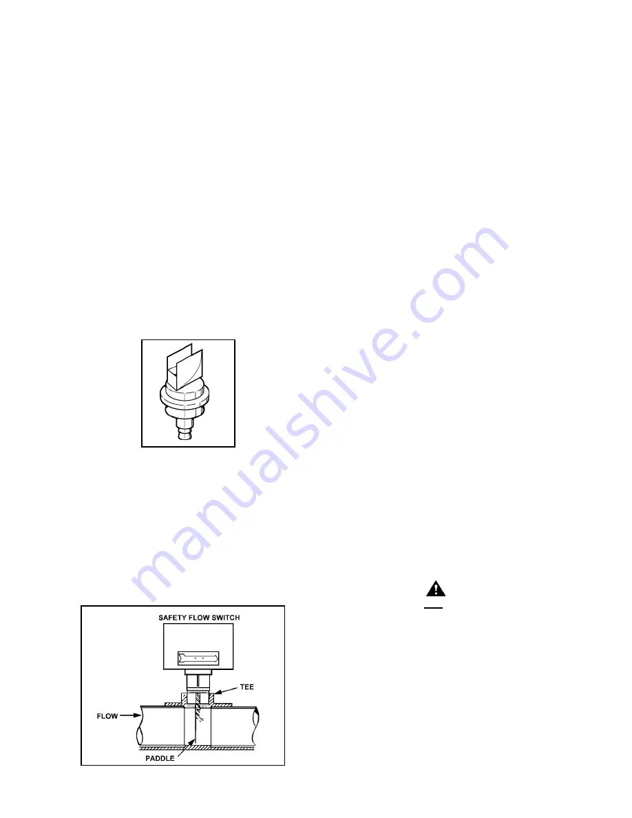
WATER FLOW SWITCH
The Water Flow Switch (WFS) fig. 6, is installed at the boiler water
outlet to prevent main burner operation in the event of inadequate
water flow through the boiler. The WFS is a single-pole, normally
open switch that will close its contacts when an increasing water
flow rate of approximately 25 GPM (1.61 lps) is encountered. The
contacts will open when the flow rate drops below this setting,
extinguishing the main burner flames (if boiler is running) or the
boiler will not start up.
FIGURE 6. WATER FLOW SWITCH (WFS)
AIR SHUTTER
The blower is equipped with an air shutter assembly for fine
adjustment of the air to gas ratio The assembly consists of a
shutter flange and the air shutter. The shutter may require
adjustment to achieve ideal start-up characteristics when fine tuning
the boiler for correct combustion specifications. Refer to the
Start-Up Procedures, part number 192077 Rev. 1, for the proper
combustion specifications and limits. If necessary, the shutter
may be adjusted by loosening the two nuts used to hold the shutter
and blower adapter assembly in place on the inlet of the blower.
Once the unit is set to the specifications called for in the Start-Up
Procedures, tighten the nuts to lock the shutter in place.
BLOWER SPEED CONTROL
The Blower Speed Control (BSC) permits variation of speed of
the blower during boiler (LB/LW-500 only) start-up. When the
1502 Control Board energizes the igniter, the BSC will lower the
speed (RPM) of the blower to a preset level. This lower speed
will be maintained until the igniter is de-energized by the Control
Board. Then, the blower will return to its normal operating speed.
COMBINATION GAS CONTROL
The Combination Gas Control (CGC) is a gas valve or valves that
controls the supply of gas to the main burner during operation of
the boiler. The CGC includes a manual main shutoff valve, two
(2) automatic valves and a pressure regulator, see figure 15.
The two-position gas control knob has “ON” and “OFF” positions
that allows or prevents the flow of gas to the main burner,
respectively. The first automatic valve is solenoid operated and
opens and closes when the main valve terminal on the Control
Board is energized or de-energized, respectively. The second
automatic valve is diaphragm operated and opens under control
of the pressure regulator and closes if gas or power supply is
interrupted. The pressure regulator is adjustable and maintains
an almost constant gas outlet pressure under wide fluctuations
in gas supply pressure.
MANUAL RESET LIMIT (E.C.O)
This device prevents the water temperature from exceeding 250°F
(121°C). It is located in the outlet waterway within the outlet
temperature sensing device and is monitored by the Control
Board. Commonly referred to as the “emergency cut out”, it is a
manually resettable control. The “ADJUST”, “SELECT” or
“ENTER/RESET” button on the display board must be depressed
to reset the unit if the water temperature reaches this limit. See
figure 20.
CAUTION
LIMIT CONTROLS ARE NOT TO BE USED AS A THERMOSTAT OR
OPERATING CONTROL.
AUTOMATIC RESET LIMIT
This limit is a safety device in series with the ignition system. Set
the limit control to a minimum of 30°F (16°C) above the maximum
designed system temperature. If the boiler outlet water
temperature should exceed the automatic reset limit setting, the
main gas valves will close. The automatic reset limit control is
factory set at 180°F (82°C) and has an adjustable range from
110 to 240°F (43° to 116°C). The operating differential is also
adjustable from 5 to 50°F (3° to 28°C).
ON/OFF SWITCH
The ON/OFF Switch is a single-pole, single-throw rocker switch.
This switch provides 120V from the line source to the boiler.
Содержание LB 1000
Страница 22: ...22 FIGURE 16 CONNECTION DIAGRAM ...
Страница 23: ...23 FIGURE 17 SCHEMATIC DIAGRAM ...


