Legend LB 1000 Скачать руководство пользователя страница 17

17

Manifold headers are recommended for split systems with or
without zone values and also those installations with zone
circulators.  If the system is to be split at remote points, good
practice requires special attention be given to main pipe sizing
to allow balancing of water flow.

5. COOLING PIPING

When the boiler is used in conjunction with a refrigeration
system it must be installed so that the chilled medium is piped
in parallel with the boiler.  Appropriate flow control valves,
manual or motorized, must be provided to prevent the chilled
medium from entering the boiler.

Water temperature in the heating system must be reduced to
less than 100°F (38°C) before cooling system is started, or
damage to the chiller unit may occur.

If the boiler is connected to chilled water piping or its heating
coils are exposed to refrigerated air, the boiler piping system
must be equipped with flow valves or other automatic means
to prevent gravity circulation through the boiler during the
cooling cycle.

Primary/secondary pumping of both the chiller(s) and the
boiler(s) is an excellent winter-summer change-over method,
because cooling flow rates are so much more than heating
flow rates. In this way each system (heating or cooling) is
circulated independently.

6. CIRCULATING PUMP

FOR HOT WATER HEATING SYSTEMS - LB MODELS

, the

circulating pump is NOT provided and must be field-installed.

NOTE:  If a system pump is to be installed on a Legend LB
model, the maximum rating of the pump motor must not
exceed 1 hp.

INTERNAL CONTAMINANTS

The hydronic system must be internally cleaned and flushed after
a new or replacement boiler has been installed, to remove
contaminants that may have accumulated during installation. This
is doubly important when a replacement boiler is installed into
an existing system where Stop Leak or other boiler additives
have been used.

Failure to clean and flush the system can produce acid
concentrations that become corrosive, cause gases to form that
block water circulation or lead to formation of deposits on the
boiler surfaces, any of which could result in damage to the system
and circulator.

All hot water heating systems should be completely flushed with
a grease removing solution to assure trouble-free operation. Pipe
joint compounds, soldering paste, grease on tubing and pipe all
tend to contaminate a system

Failure to flush contaminants from a system can cause solids to
form on the inside of boiler exchangers, create excessive amounts
of air and other gases to block circulation, foul various system
accessories and even deteriorate circulation seals and impellers.

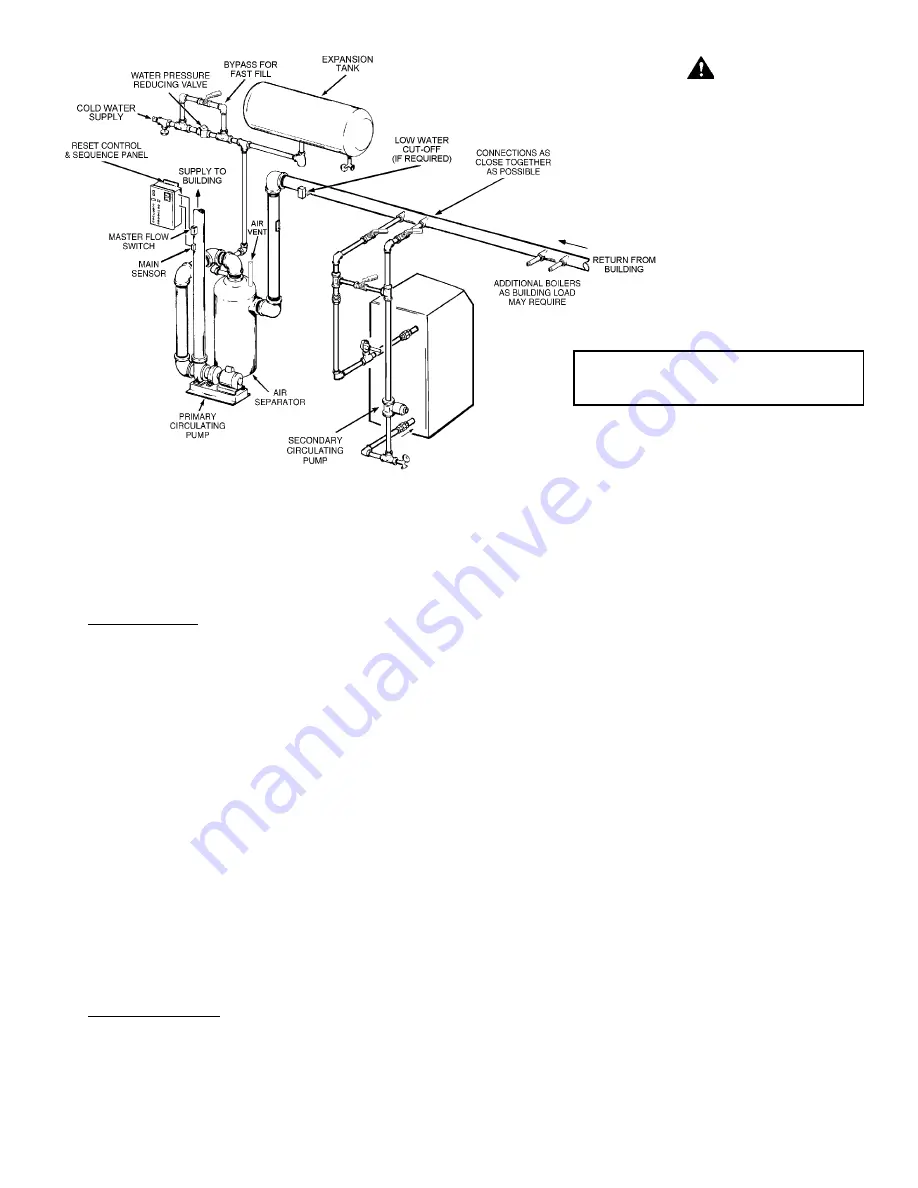
HOT WATER SUPPLY BOILER SYSTEM-

GENERAL WATER LINE CONNECTIONS

This section provides detailed installation diagrams for a typical
method of application for the unit.

Piping diagrams will serve to provide the installer with a reference
for the materials and methods of piping necessary for installation.
It is essential that all water piping be installed and connected as
shown on the diagrams. Check the diagrams to be used
thoroughly before starting installation to avoid possible errors
and to minimize time and material cost.

It is essential that all water piping be installed and connected as
shown on the diagrams.  Check the diagrams to be used
thoroughly before starting installation to avoid possible errors
and to minimize the time and material cost.

FIGURE 12.  TYPICAL PRIMARY, SECONDARY PIPING

• INSTALL IN ACCORDANCE WITH ALL LOCAL CODES.

• WHEN BLOW DOWN VALVE IS REQUIRED, INSTALL

IN PLACE OF THE DRAIN VALVE SHOWN.


DANGER

TEMPERATURE SETTING SHOULD NOT EXCEED
SAFE USE TEMPERATURE AT FIXTURES.  SEE
WATER TEMPERATURE CONTROL WARNING ON
PAGE 28.  IF HIGHER PREHEAT TEMPERATURES
ARE NECESSARY TO OBTAIN ADEQUATE
BOOSTER OUTPUT, ADD AN ANTI-SCALD VALVE
FOR HOT WATER SUPPLIED TO FIXTURES.

Содержание LB 1000

Страница 1: ...tely call your gas supplier from a neighbor s phone Follow the gas supplier s instructions If you cannot reach your gas supplier call the fire department Installation and service must be performed by a qualified installer service agency or the gas supplier PRINTED IN U S A 1004 GAS FIRED POWER BURNER COPPER BOILERS FOR HYDRONIC HEATING AND HOT WATER SUPPLY INSTALLATION OPERATION MAINTENANCE LIMITE...

Страница 2: ...152 6 152 7 178 7 178 Blower Inlet Diam 4 102 4 102 4 102 4 102 6 152 6 152 A 53 1346 53 1346 53 1346 53 1346 60 1 2 1537 60 1 2 1537 B 23 584 23 584 23 584 23 584 27 1 8 689 27 1 8 689 C 32 813 32 813 32 813 32 813 38 3 16 970 38 3 16 970 D 13 1 2 343 13 1 2 343 13 1 2 343 13 1 2 343 13 3 4 349 13 3 4 349 E 4 3 8 111 4 3 8 111 4 3 8 111 15 1 2 394 F 3 1 4 83 3 1 4 83 3 1 4 83 3 1 4 83 G 6 3 8 162...

Страница 3: ...24 9291 6194 5162 4646 3716 3441 3097 2655 2581 LB LW 750 Natural 750 000 GPH 4545 4091 2727 2273 2045 1636 1515 1364 1169 1136 220 LPH 17206 15485 10324 8603 7743 6194 5735 5162 4424 4301 LB LW 750 Propane 675 000 GPH 4091 3682 2455 2045 1841 1473 1364 1227 1052 1023 198 LPH 15485 13937 9291 7743 6968 5575 5162 4646 3982 3871 LB LW 1000 Natural 1 000 000 GPH 6061 5455 3636 3030 2727 2182 2020 181...

Страница 4: ...ating Pump Adjustment Procedure 32 Display Current Mode 33 DisplayTotal Cycle Count 33 Tank ProbeTemp Set PointAdjustment Procedure 33 Display Board LED Indicators 34 TROUBLESHOOTING Short Cycling 34 Hard Starts 34 Troubleshooting Error Codes 34 LIMITEDWARRANTY 36 In addition to these instructions the boiler s shall be installed in accordance with those installation regulations in force in the loc...

Страница 5: ...recommended IF YOU EXPERIENCEAN OUT OF GAS SITUATION DO NOT TRY TO RELIGHT APPLIANCES YOURSELF Call your local service agent Only trained LP professionals should conduct the required safety checks in accordance with industry standards HIGH ALTITUDE INSTALLATIONS WARNING INSTALLATIONS ABOVE 2000 FEET 600 M REQUIRE REPLACEMENT OF THE BURNER ORIFICE IN ACCORDANCE WITH SECTION 8 2 1 OF THE NATIONALFUE...

Страница 6: ...C IGNITION CONTROL The Legend 2000 is controlled by the WHC 1502 ignition system fig 2 The WHC 1502 is a solid state ignition control that ignites the main burner by energizing the Hot Surface Ignitor fig 3 The ignition control system continuously monitors the current of the ignitor and will not allow gas to enter the main burner until current flow reaches the preset ignition temperature threshold...

Страница 7: ...ions called for in the Start Up Procedures tighten the nuts to lock the shutter in place BLOWER SPEED CONTROL The Blower Speed Control BSC permits variation of speed of the blower during boiler LB LW 500 only start up When the 1502 Control Board energizes the igniter the BSC will lower the speed RPM of the blower to a preset level This lower speed will be maintained until the igniter is de energiz...

Страница 8: ...anifold This will help to drain the heat exchanger Additional drain valves must be obtained and installed on each boiler and tank for draining purposes see figures 12 13 and 14 SAFETY RELIEF VALVE Your local code authority may have other specific safety relief valve requirements not covered below WARNING THE PURPOSE OF A SAFETY RELIEF VALVE IS TO AVOID EXCESSIVE PRESSURE OR TEMPERATURE INTO THE ST...

Страница 9: ...barrier etc air for combustion ventilation and draft hood dilution must be obtained from outdoors The T P relief valve must comply with the applicable construction provisions of the Standard for Relief Valves and Automatic Gas Shutoff Devices for Hot Water Supply Systems ANSI Z21 22 1999 or CAN CSA B149 1 00 or most recent edition The T P relief valve must be of the automatic reset type and not em...

Страница 10: ...than 1 square inch per 7 000 BTUH 315 mm2 KW up to and including 1 000 000 BTUH plus 1 square inch per 14 000 BTU 158 mm2 kW in excess of 1 000 000 BTUH This opening s shall be located at or ducted to a point neither more than 18 457 mm nor less than 6 inches 152 mm above the floor level Where power vented equipment is used in the same room as the boiler sufficient air openings must be supplied UN...

Страница 11: ...the National Fuel Gas Code ANSI Z223 1 or CSA B149 1 00 and latest addenda The vent system must not have external runs greater than that allowed by local codes or the National Fuel Gas Code 2 AL 29 4C sections and fittings MUST be used for the entire length of the exhaust system alternatives such as galvanized pipe PVC CPVC or Type B Vent sections must not be used 3 Install a AL 29 4C drain fittin...

Страница 12: ... wall or parapet it must extend a minimum of 2 610 mm above the wall or parapet Joints are not joined to show vent pipe orientation FIGURE 9 VERTICAL TERMINATION FIGURE 9A THROUGH THE WALL TERMINATION TWT NOTES Joints are not joined to show vent pipe orientation ...

Страница 13: ... REQUIREMENTS 1 The vent system must terminate at least three 3 feet 1 0 m and no more than six 6 feet 2 0 m above the roof line and no closer than ten 10 feet 3 0 m from any wall or vertical structure If the exhaust vent terminal is within 10 3 0 m of a wall or parapet it must extend a minimum of 2 610 mm above the wall or parapet See figures 9 and 11A 2 For direct vent installations the total di...

Страница 14: ...t exchanger and icing of the combustion air intake during severe cold weather To prevent the recirculation of flue gases maintain as much distance as possible between the combustion air intake and the exhaust vent terminal NOTES If the exhaust vent terminal is within 10 3 0 M of a wall or parapet it must extend a minimum of 2 610 MM above the wall or parapet Joints are not joined to show vent pipe...

Страница 15: ...MAX AL 29 4C HORIZONTAL AIR INTAKE PVC PIPE 90 EQUIVALENT FEET 27 4M AIR INTAKE TERMINAL NOTES IF THE EXHAUST VENT TERMINAL IS WITHIN 10 3 0M OF A WALL OR A PARAPET IT MIUST EXTEND A MINIMUM OF 2 0 6M ABOVE THE WALL OR PARAPET ON SIDEWALL VENT INSTALLATION REFER TO FIGURE 7 FOR SPACING SPECIFICATIONS FOR EXHAUSTAND AIR INTAKE PIPE INSTALLATIONS CLEARANCES SUPPORT ETC REFER TO FIGURES 11 AND 11A VE...

Страница 16: ...d practice requires that all heavy piping etc be supported Figure 12 shows a typical primary secondary piping method This is the preferred piping method for most copper fin tube boilers Other piping methods however may provide good system operation A prime concern when designing heating systems is the maintenance of proper flow through the unit during boiler operation The secondary pump should be ...

Страница 17: ...stem where Stop Leak or other boiler additives have been used Failure to clean and flush the system can produce acid concentrations that become corrosive cause gases to form that block water circulation or lead to formation of deposits on the boiler surfaces any of which could result in damage to the system and circulator All hot water heating systems should be completely flushed with a grease rem...

Страница 18: ...O OBTAIN ADEQUATE BOOSTER OUTPUT ADD AN ANTI SCALD VALVE FOR HOT WATER SUPPLIED TO FIXTURES INSTALL THERMAL EXPANSION TANK ON COLD WATER SUPPLY LINE IF CHECK VALVE OR PRESSURE REDUCING VALVE IS USED IN SUPPLY INSTALL INACCORDANCE WITHALL LOCALCODES PRESSURE RELIEF VALVE RATING SHOULD NOT EXCEED PRESSURE CAPACITYOFANYCOMPONENTIN THE SYSTEM INSTALLTEMPERATURE PRESSUREGAUGEANDPRESSURERELIEFAS CLOSE T...

Страница 19: ...at the rear of the unit Field wiring in conduit is required from the plug wires to the tank probe sensor wires See figure 7 TANK PROBE SET POINT ADJUSTMENT When the temperature sensor is installed in a water tank and the sensor is used with the WHC1502 system the controller will monitor and control the temperature of the water at the sensor location Setting the temperature is accomplished through ...

Страница 20: ...gravity of 0 60 and a heating value of 1 000 BTU ft3 approximately that of Natural Gas Table 8 is based on a pressure drop of 0 5 inches water column 0 124 kPa and a gas with a specific gravity of 1 53 and a heating value of 2 500 BTU ft3 approximately that of Propane Gas No additional allowance is necessary for an ordinary number of fittings Where it is necessary to use more than the average numb...

Страница 21: ...728 00012 636 00011 700 00011 232 00010 452 000 9 360 000 8 580 000 7 800 000 7 176 000 kW 10 508 7 219 5 848 4 980 4 432 4 021 3 701 3 427 3 290 3 061 2 741 2 513 2 284 2 102 Table 7 Suggested Pipe Size For Multiple Gas Appliances Natural Gas Nominal Maximum Capacity of Pipe in BTU hr and kW for Gas Pressures of 14 in W C 0 5 psi or Less and Iron Pipe a Pressure Drop of 0 5 in W C based on 0 60 S...

Страница 22: ...22 FIGURE 16 CONNECTION DIAGRAM ...

Страница 23: ...23 FIGURE 17 SCHEMATIC DIAGRAM ...

Страница 24: ...NTROLLER IS SATISFIED OTHERWISE THE WARRANTY IS VOID AS STIPULATED IN THE LIMITED WARRANTY IN THIS INSTALLATION MANUAL IF ANY OF THE ORIGINAL WIRE AS SUPPLIED WITH THE APPLIANCE MUST BE REPLACED IT MUST BE REPLACED WITH TYPE 105 C WIRE OR ITS EQUIVALENT The LEGEND 2000 must be connected to a single phase independent line source that is NOTE For proper boiler performance it is important that the Le...

Страница 25: ...N IGNITION DEVICE WHICH AUTOMATICALLY LIGHTS THE BURNER DO NOT TRY TO LIGHT THE BURNER BY HAND B BEFORE LIGHTING SMELL ALL AROUND THE APPLIANCE AREA FOR GAS BE SURE TO SMELL NEXT TO THE FLOOR BECAUSE SOME GAS IS HEAVIER THAN AIR AND WILL SETTLE ON THE FLOOR WHAT TO DO IF YOU SMELL GAS DO NOT TRY TO LIGHT ANY APPLIANCE DO NOT TOUCH ANY ELECTRIC SWITCH DO NOT USE ANY PHONE IN YOUR BUILDING IMMEDIATE...

Страница 26: ...NOB NEVER USE TOOLS IF THE KNOB WILL NOT PUSH IN OR TURN BY HAND DON T TRY TO REPAIR IT CALL A QUALIFIED SERVICE TECHNICIAN FORCE ORATTEMPTED REPAIR MAY RESULT INAFIRE OR EXPLOSION D DO NOT USE THIS APPLIANCE IF ANY PART HAS BEEN UNDER WATER IMMEDIATELY CALL A QUALIFIED SERVICE TECHNICIAN TO INSPECT THE APPLIANCE ANDTO REPLACEANYPARTOF THE CONTROLSYSTEM AND ANY GAS CONTROL WHICH HAS BEEN UNDER WAT...

Страница 27: ...west setting so that the boiler will not call for heat 2 Refer to Figure 15 and MANIFOLD PRESSURE CONNECTIONS for the proper method of measuring manifold pressure 3 Reset the system controller dial to desired setting ensure ON OFF switch is ON The main burner will ignite 4 With the main burner firing adjust the pressure if necessary by turning the pressure regulator adjusting screw with a slot typ...

Страница 28: ...ater applications that lower water temperatures be used to avoid the risk of scalding It is further recommended in all cases that the water temperature be set for the lowest temperature which satisfies the user s hot water needs This will also provide the most energy efficient operation of the boiler and minimize scale formation in the heat exchanger thus prolonging the life of the boiler SETTING ...

Страница 29: ...s including Low Water Cutoffs used in conjunction with this boiler should receive periodic every six months inspection to assure proper operation A Low Water Cutoff device of the float type should be flushed every six months All relief valves should be inspected and manually operated at least twice a year VENTING MAINTENANCE It is recommended that the venting system be checked monthly by a qualifi...

Страница 30: ...he condensate drains and tubes at least once a month and insure they will allow the free flow of condensate at all times The system must be inspected more frequently in cold weather if the drain system is located in an area such as along the floor where freezing temperatures are likely to occur The condensate drain system must be protected against freezing Contact a qualified service agent to insp...

Страница 31: ...power this LED will not light Improperly connecting the input power may result in a false flame sensor failure FUSE PROTECTION The 24 VAC circuitry is protected with a 3 amp auto fuse If the fuse opens a red LED located near the fuse will light If the red LED is illuminated replace the fuse Repeated failure of the fuse is an indication of possible damage to the ignition control Note An extra fuse ...

Страница 32: ...0 F 115 C and once again increase decrease in value for as long as the ADJUST push button is pressed NOTE The boiler must complete a full cycle in order for the new setting to take effect If the unit is turned off prior to a complete cycle the setting will be lost and the previous setting will remain in effect NOTE If the tank probe is connected to the system the appliance Set Point temperature wi...

Страница 33: ...circulate function With the Display Board the user has the capability to choose between a 45 90 or 180 second post circulate time period or turn the pump on continuously This provides flexibility in selecting the post circulate time to meet specific installation requirements and improves the efficiency of the circulating pump operation NOTE It is recommended that intermittent post circulate pump m...

Страница 34: ...lower Fail Indicates an error malfunction in the blower motor circuit Circulate Fail Indicates an error malfunction in the circulating pump circuit Ignition Fail Indicates a malfunction in the ignition system circuit TROUBLESHOOTING SHORTCYCLING Shortcycling is a condition where the boiler starts up and shuts down frequently in a short time period This usually indicates that an abnormal operating ...

Страница 35: ...t both See previous pages The display defaults to the outlet water temperature under normal circumstances On LW models however the display defaults to the tank probe temperature once the probe supplied with the unit is connected to the control board Set the unit s automatic reset limit at least thirty 30 F 17 C above the tank temperature setting on hot water supply applications However the tempera...

Страница 36: ...ler under state or provincial law are limited to one 1 year duration for the heater or any of its parts Some states and provinces do not allow limitations on how long an implied warranty lasts so the above limitation may not apply to you 5 CLAIM PROCEDURE Any claim under this warranty should be initiated with the dealer who sold the boiler or with any other dealer handling the warrantor s products...

Отзывы: