


Hardware
installation manual of the multi-axis drive MX3660
Leadshine Technology Co., Ltd
Leadshine America, Inc.
Page 6/25
11/F, Block A3, iPark,
No.1001 Xueyuan Blvd, Nanshan District, Shenzhen, China
25 Mauchly, Suite 318, Irvine, CA 92618, USA
Tel:
86-755-26409254
Fax: 86-755-26402718
Tel: 1-949-608-7270
Fax: 1-949-608-7298
Web
:
www.leadshine.com
Email:
Web:
www.leadshine.com
Email:
5.
Dimensions
162±0.5
169±1.5
19
.5
±0
.3
54
.5
±0
.3
77
.5
±1
.5
5
162±0.5
16
±0
.2
37
±1
.5
5
3.5
3.5
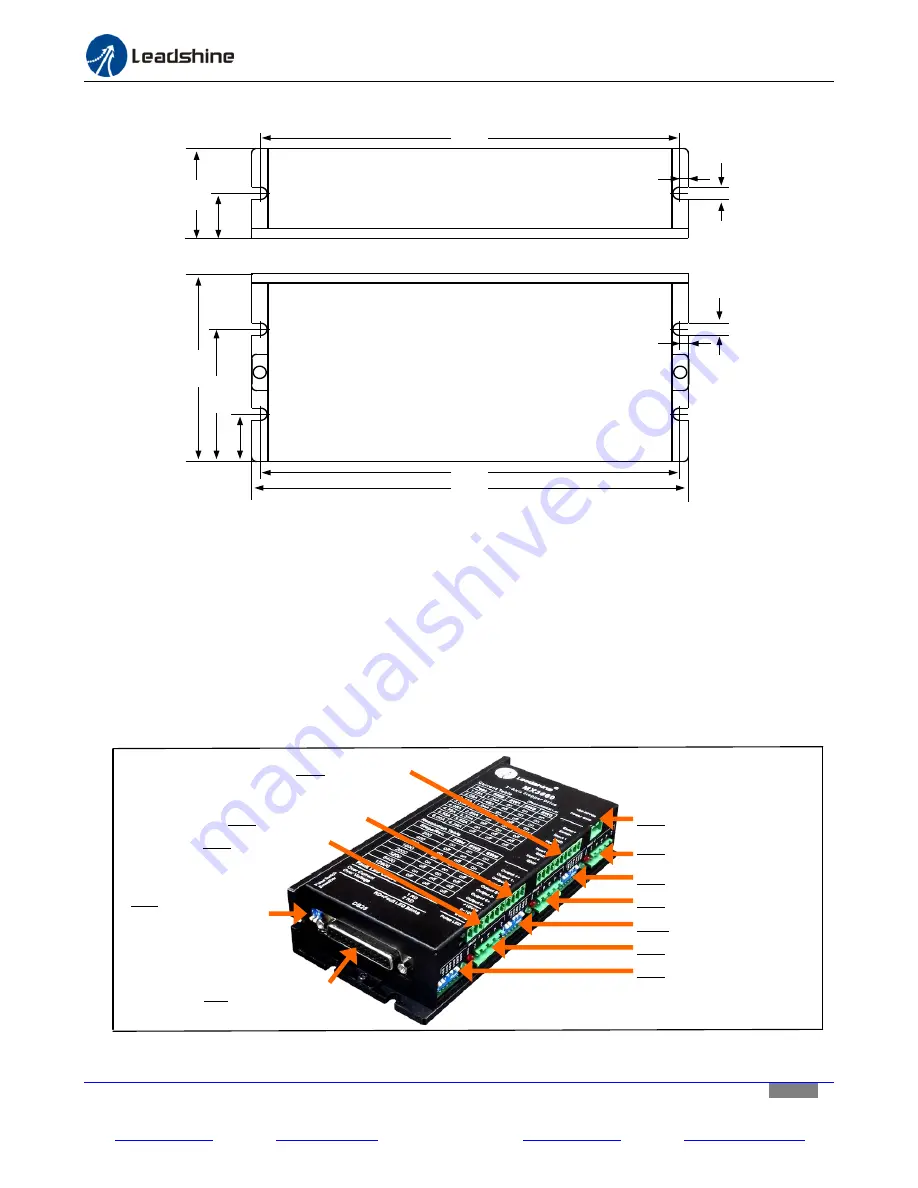
Figure 2 MX3660 dimensions
6.
Get Started
Before you start hardware connection, refer to the following MX3660 layout diagram (figure 3) for connector/DIP
switch location. Read the MX3660 datasheet for each connector explanation. Then, get the following prepared:
A 24-54 VDC power supply.
Up to 3 stepper motors depending on how many axes that MX3660 will power in your application.
A source of step signals, such as a motion controller, PLC, or a PC-based control system (Mach3/4, EMC, etc.).
A small flat blade screw driver for tightening the screw connectors of the MX3660.
Whatever optional external devices needed to be controlled through the built-in outputs and inputs.
Figure 3
MX3660 layout
CN1:
DB25 Connector
DP3:
Z-Axis DIP switch
CN5:
Z-Axis Motor Connector
DIP2:
Y-Axis DIP switch
DP1:
X-Axis DIP switch
CN3:
X-Axis Motor Connector
CN4:
Y-Axis Motor Connector
CN8:
Analog Output
CN7:
Digital Outputs
CN6:
Digital Inputs
CN2:
Power Connector
DP4:
Pulse Switch &
Smoother switch


