79
User
Manual
for
ELD2
Servo
positioning related data of path-0
)
17 4D
the CRC verification code, do not have to directly input, click the corresponding send area
verification button automatically generated
The final analysis is as follows: speed is 1000r/min, acceleration and deceleration time is 100ms,
Speed mode
7.5 Upper computer operation
Upper computer is used for drive parameter setting and save, steps for debugging is:
1. Three-loop control parameters. According to the position mode debugging method.
2. Set the work mode to be PR mode
(
Pr0.01=0
),
Internal SERVO-enabled
(
Pr4.00=383
),
set the
distribution of IO register P4.0-P4.13) Confirm the running direction and so on.
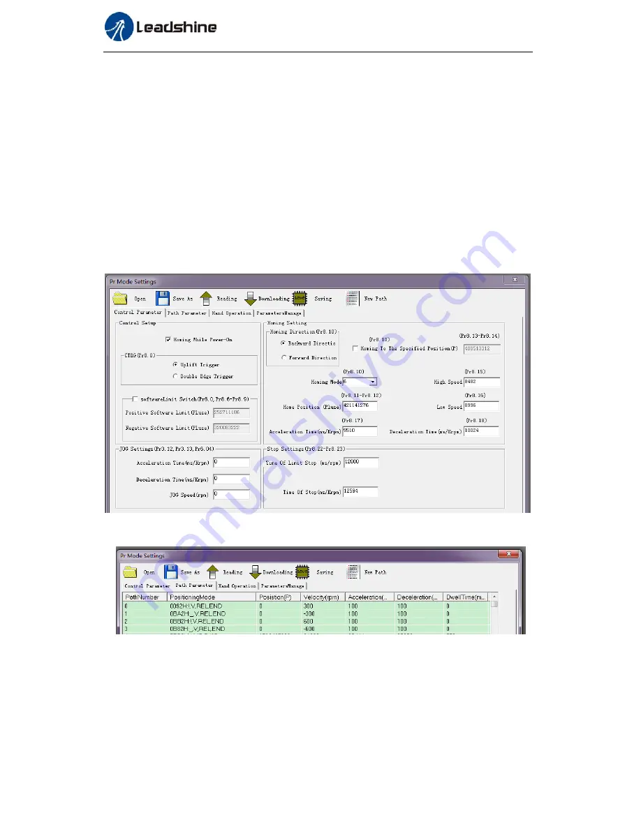
3. Setting up the PR basic control parameters through upper computer's " Pr-MODE " interface.
Include: trigger setting, software limit, JOG function, homing function, e-stop function and so on.
4. Setting up the PR positioning path parameters through upper computer's " Pr-MODE " interface,
include:
For the convenience of the positioning model expressing, use mnemonic symbol to express, such as:
_P , ABS , SJ1 means that path is position addressing, position value is absolute position, jump
to No.1 path with delay, and can not interrupt running.
!V , ABS , SJ1 means that path is speed running, jump to No.1 path with delay, and can
interrupt running.
_HOME means that path is homing movement.


