A
A
C
C
S
S
6
6
0
0
6
6
D
D
i
i
g
g
i
i
t
t
a
a
l
l
A
A
C
C
S
S
e
e
r
r
v
v
o
o
d
d
r
r
i
i
v
v
e
e
M
M
a
a
n
n
u
u
a
a
l
l
R
R
e
e
v
v
1
1
.
.
0
0
Tel: (86)755-26434369
46
Website: www.leadshine.com
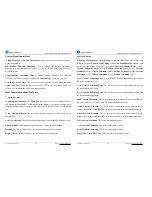
Erase All!: Erase All!
button. The user can clear all error(s) including error
history by clicking this button.
7.Using Tips
Change PPR by Electronic Gear
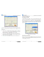
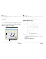
PPR(pulses per revolution) is the counts/pulses to make motor move one turn. If the
default PPR can not satisfy your application, a way to change it is setting electronic
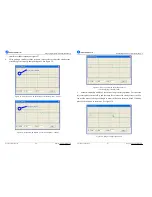
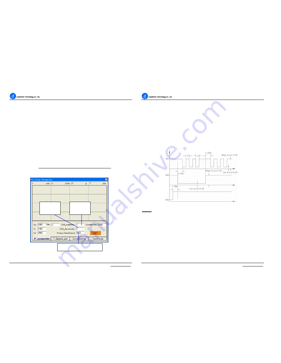
gear in ProTuner as shown in figure 50. You can set this parameter in the position
tuning window by select
Tuning->PositionLoop->P_parameter.
For ACS606, the
actual PPR can be calculated by the following formula:
numerator
CAM
ator
deno
CAM
resolution
Encoder
PPR
_
min
_
_
4
×
×
=
Figure 50: Electronic gear and position following error setting
Numerator
of Electronic
Denominator
of Electronic
Position following error limit
A
A
C
C
S
S
6
6
0
0
6
6
D
D
i
i
g
g
i
i
t
t
a
a
l
l
A
A
C
C
S
S
e
e
r
r
v
v
o
o
d
d
r
r
i
i
v
v
e
e
M
M
a
a
n
n
u
u
a
a
l
l
R
R
e
e
v
v
1
1
.
.
0
0
Tel: (86)755-26434369
47
Website: www.leadshine.com
Position following Error Limit
The ACS606 will activate a position following error if position error between
command and encoder feedback exceeds the setting limit value. To set the limit
value, please select
Tuning->PositionLoop->P_parameter
and find the Position
FollowingErrLimit
edit box. See figure 50.
Sequence Chart of Control Signals
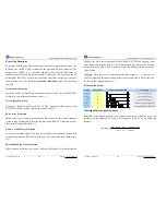
In order to avoid some fault operations and deviations, PUL, DIR and EN should
abide by some rules, shown as the following figure:
Figure51: Sequence chart of control signals
Notes:
a)
t
1
: EN must be ahead of DIR by at least 5
µ
s. Usually, ENA is NC (not
connected). See
Connections
section for more information.
b)
t
2
: DIR must be ahead of PUL active edge by at least 5
µ
s to ensure correct
direction.
c)
t
3
: Pulse width not less than 0.85
µ
s;
d)
t
4
: Low level width not less than 0.85
µ
s.

