LAUNCH KES-200 Ignition Waveform
D-6
The user may press [8] directly or use [
▲
] [
▼
] keys
to select [Intake manifold vacuum] function, and then
press [ENTER] key to start the test as shown in
Fig.3-15.
Fig.3-15
If the cylinder 1 signal cable is not connected well, the
screen will display a message as shown in Fig.3-16.
Fig.3-16
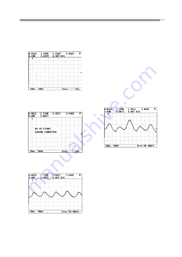
The normal waveform of the 4-cylinders engine is as
shown in Fig.3-17.
Fig.3-17
The waveform of the cylinder connected to the
cylinder 1 signal cable is displayed on the left side of
the screen. If the firing order of the engine is 1-3-4-2,
then the displayed waveforms are corresponding to 1,
3, 4 and 2 respectively. The waveform displayed in
Figure 5 is a normal one; it is shown that the intake
manifold vacuum for each cylinder is basically the
same during the air intake process, which indicates
the air intake system and the cylinder condition are
normal.
The waveform displayed in Fig.3-18 is an abnormal
one; it is shown that the intake manifold vacuum for
cylinder 3 evidently drops. Since the intake process of
cylinder 3 is exactly the exhaust process of cylinder 4,
we can easily judge that the airproof performance of
cylinder 4 is not good, the exhaust gas may enter into
the intake manifold and thus makes the intake air
vacuum of cylinder 3 drop.
Fig.3-18


