15 SELECTION OF WIRES AND CONNECTION DIAGRAMS
EC-3100/U
L+
L-
MC
GA
SP
T
GS
VS
VZA
GZA
GA
MC
SP
GS
T
VS
KZ
GZ
PANEL 1
MC
MG
SG
SP
T
GD
VZ
GZ
XZ
T1
GS1
MC1
SP1
GA1
CP-31xx
CS
VS
C4-
C3+
C3-
C3+
C2-
C1+
C1-
CS
C4+
V
G
L+
L-
GS
VS
MRL-1 module
CVP-2
input of video signal
from the panel
MON 4
To the next distributors
or change-over switches
CVR-x
C+
L+
C-
L-
X+
X-
VS1
KZ1
GZ1
C+
C-
PANEL 2
MC
MG
SG
SP
T
GD
VZ
GZ
XZ
T2
GS2
MC2
SP2
GA2
CP-31xx
VS
-
+
Y+
Y
-
to another
CVR-x
230 V AC
14,5 V AC
0,8 A
12 V AC
1 A
White
Brown
AC4
AC3
AC2
AC1
Brown
Brown
Electro-catch
Electro-catch
MON 3
MON 2
MON 1
Electronic cassette
power supply
230V
C+
C-
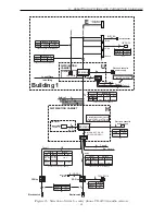
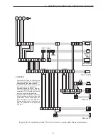
Figure 38: Doorphone system CD-3100 in video version
monitor
feeder*
PLUG RJ 45
UTP
NOTE!
-
in every monitor connected to distributor
CVR-1 jumper Z1 should be in position
UTP+TERM!
-
in distributor at the end of C+ C- line set
JP1 to the one of three possible value. This
value should be selected experimentally to
get the best picture on monitor screens.
1
8
8
1
Distributor CVR-1
brown
8
brown - white
7
green
6
blue - white
5
blue
4
green - white
3
orange (NC)
2
orange - white (NC)
1
L+
VC
GV/GC
C+
L-
C-
MV-64xx
MVC-6x5x
* for MV-64xx - 15V DC/0.8A
for MVC-6x5x - 13.5V DC/1A
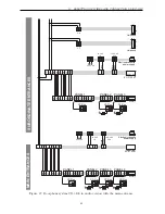
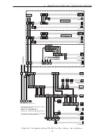
Figure 39: System CD-3100 video. Connection of monitor - description of plug and socket
RJ-45 used for connecting the monitor in use with CVR-1 distributor.
62


