6.8 Installation of distributor CVR–1 and CVR–2
6 INSTALLATION AND ACTIVATION
Apply for CVR-2
Distributor require 15V DC stab./4A external power supply adaptor which allowed
to load each of 4 outputs by the current of 1A to supply monitors (+15V, GND).
It is not recommended to use with MV645x series monitors.
It is recommended that wires sections connecting distributor with monitor connected
to sockets MON1 and MON2 have comparable length. The same principle refers
to wires connected to sockets MON3 and MON4.
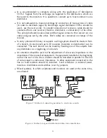
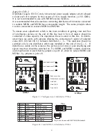
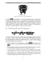
To ensure wave adjustment, which is the main condition of getting clear and free
of interference picture, at the end of this line load in form of resistor should be
connected of value equal to the impedance the wire used in this line. In distrib-
utors there are joints with jumpers allowing the connection of resistor of selected
value (100, 124 lub 136
Ω
). between terminals C+, C-. This resistance should be
switched only in one distributor which was installed at the end of line C+,C-. If
distortion is visible on the screen or the picture is not clear or pale amplifying and
signal correction should be switched on. For MON1 and MON2 outputs correction
and amplification are switched by jumpers in joint J2, while for output MON3 and
MON4 – by jumpers in joint J3.
JP1
JP2 JP3
MON1
MON2
MON3
MON4
W1
W2
JP1
JP2
JP3
MON
1
MON
2
MON
3
MON
4
G
+
W1
W2
JP2
JP3
Band correction
Without band correction
JP1
Input impedance 136
Input impedance 124
Input impedance 100
Gain 0 dB
Gain +4 dB
Gain +2 dB
CVR-1
CVR-2
Figure 13: Configuration of distributor CVR-x
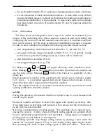
Plug in accordance with EIA/TIA 568B standard
nr clamp color
1
T +
orange-white
2
T -
orange
3
Vc
green-white
4
L +
blue
5
L -
blue-white
6
GND
green
7
C +
brown-white
8
C -
brown
uniwersal output
uniwersal output
power supply: +10VDC
uniphone line
ground
video signal
video signal
function
uniphone line
8
1
Plug
1 8
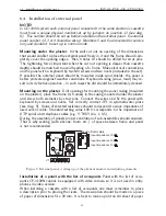
Figure 14: Joint MON-1 of distributor CVR-1
23

