background image

14 DIMENSIONS OF ELEMENTS

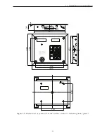
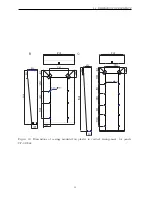
Figure 28: Dimensions of panels CP-3100xx with a frame for mounting under plaster

53

Содержание CD-3100 Series

Страница 1: ...CD 3100xx INSTALLATION SERVICE AND PROGRAMMING INSTRUCTION DIGITAL ENTRY PHONE SYSTEM ...

Страница 2: ...o version 17 6 4 Installation of external panel 19 6 5 Installation of electronic cassette and power supply adaptor 20 6 6 Assembly of MRL 1 modules 21 6 7 Assembly of CVP 2 commutator 21 6 8 Installation of distributor CVR 1 and CVR 2 22 6 9 Installation of monitor and additional cameras 24 6 10 Installation and programming of uniphone 24 6 11 Adjustment of the doorphone system CD 3100 24 6 12 Ac...

Страница 3: ...usage 44 8 5 Using coded lock function 44 8 6 Using electric keys 44 8 7 User s menu 45 9 Restoring the initial settings 47 10 Maintenance of entry phone 48 11 Conformity with previous versions 48 12 Messages about faults 49 13 Technical data 49 13 1 Degree of protection 49 13 2 Description of terminals 49 14 Dimensions of elements 52 15 Selection of wires and connection diagrams 57 2 ...

Страница 4: ...Doorphone effectively protects the building from any access of unauthorized persons decreasing a risk of damage or destruction of internal infrastructure Simultaneously it enables easy and comfortable access to the building for its occupants Low cost of installation per one occupant Electronic touch key Property administrators as well as technical services can use only one key to enter all objects...

Страница 5: ...e should get acquainted with the installation and operation instruction Wiring system should be performed according to standard PN IEC 60364 1 by an authorized person It should be made in such a way as to avoid the risk of lightning Monitor should be mounted in a place that is easily accessible for users at a height of min 1 5 m in such a way as to eliminate the danger for the users and accidental...

Страница 6: ...should not be sent to RTV sets because his may result in the damage of such sets or entry phone Outside panels should not be sealed with e g silicone because it worsens ventilation and leads to corrosion 2 Installation of entry phone The following items include the most important stages of design performance and activation of an entry phone system Item numbers in instruction containing the detaile...

Страница 7: ...ernal panels were designer Panels are produced in audio and video version colour camera and LED lighting They are made of zinc coated sheet covered with powder paint or of stainless steel in all panel optical keyboard is used Panels may be equipped with an electronic touch key reader Electronic key is an alternative to a combination lock it is also a very good replacement of a traditional mechanic...

Страница 8: ...le entry phone system Uniphone LM 8W 3 is equipped with a highly effective receiver which ensures call signal louder by approx 6 dB than in standard LM 8 uniphone Uniphone LM 8W 4 has a door bell function Additional terminals in the uni phone enable the connection of bell button Pressing the button results in switching on the gong Uniphone requires additional supply Loud speaking Uniphone LG 8 and...

Страница 9: ... the next one and in the distributor at the end of bus bar the line load should be configured properly see dwg 13 page 23 Signal distributor has one input of signals L L C C with screw terminals ARK and four independent outputs with sockets RJ 45 CVR 1 or ARK CVR 2 Distributor CVR 1 does not require power supply adaptor it is supplied from mon itors connected to it although it has clamps enabling ...

Страница 10: ...n of next panels requires application of MRL 1 module Power supply Ac power supply adapter ZS K 25 01 art 0018 or TSZZM 25 021M should be used for supplying electronic cassette In CD 3100 system one external panel and one electronic cassette can be together fed from this power supply The other panels must be fed from the local feeders To supply external panels it should be used stabilized feeders ...

Страница 11: ... of occupants for panel CP 3110 NP 2521 horizontal list of occupants for panel CP 3120 NP 2522 vertical list of occupants for panel CP 3120 Accumulator The accumulator can be connected to the electronic cassette It is used to feed the doorphone installation in the case of voltage collapse in power network The accumulator is connected to the electronic cassette so in case of voltage collapse only t...

Страница 12: ...th number 2 will ring etc 4 3 Hotel numbering mode This numbering mode is meant for the buildings in which room number starts with a digit defining number of floor on which the room is located hotels resort houses dormitories etc Physical number of a uniphone is calculated according to the formula Physical number P LL XX A where P floor number LL amount of rooms on one floor value of parameter LPi...

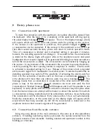
Страница 13: ...dings The following operations should be made in order to activate this mode In electronic cassette for subordinate entrance set parameter n bl block num ber in procedure P 2 to value higher then zero see dwg 33 To get connection with any apartment in this staircase the apartment number should be preceded by set number see dwg 30 The operation should be repeated for other staircases buildings Valu...

Страница 14: ...ed by the keyboard will result in entry phone ringing at one selected number 5 Configurations of entry phone operation 5 1 Basic system MRL 1 1 2 3 4 5 6 7 8 9 0 C 1 2 3 4 5 6 7 8 9 0 C 1 2 3 4 5 6 7 8 9 0 C 10 6 6 8 2 EC 3100 U CP xxxx CP xxxx CP xxxx 2 2 2 2 2 2 230V 2 230V 2 230V 4 Figure 1 Basic system audio version MRL 1 1 2 3 4 5 6 7 8 9 0 C 1 2 3 4 5 6 7 8 9 0 C CVP 2 1 2 3 4 5 6 7 8 9 0 C ...

Страница 15: ... 8 9 0 C 1 2 3 4 5 6 7 8 9 0 C 1 2 3 4 5 6 7 8 9 0 C 1 2 3 4 5 6 7 8 9 0 C 1 2 3 4 5 6 7 8 9 0 C Figure 3 Multi entrance system main entrances connection can be established with each apartment in any building or staircase By means of panels situated at slave entrances connection can be established only with the apartments located in the staircase or the building to which a given entrance is leadin...

Страница 16: ...230V 2 230V 4 MAIN ENTRANCE SUBORDINATE ENTRANCE Figure 4 System with entrance hierarchy audio version MRL 1 1 2 3 4 5 6 7 8 9 0 C 1 2 3 4 5 6 7 8 9 0 C CVP 2 1 2 3 4 5 6 7 8 9 0 C MRL 1 1 2 3 4 5 6 7 8 9 0 C 1 2 3 4 5 6 7 8 9 0 C CVP 2 1 2 3 4 5 6 7 8 9 0 C CVR 1 230V 2 2 2 2 2 2 2 8 8 8 8 8 8 8 5 6 6 8 8 4 4 4 8 8 230V 2 230V 2 230V 2 230V 2 230V 2 1 2 3 4 5 6 7 8 9 0 C 12 230V 4 EC 3100 EC 3100...

Страница 17: ...installed at such a distance it could be connected by means of the original cable To electronic cassette configured as EC 3100 U it is possible to connect from 1 up to 3 outer panels One from them can be fed from EC 3100 U whereas two others from the own local feeders To electronic cassette configured as EC 3100 H it is possible to connect from 1 up to 4 outer panels One of them can be fed from EC...

Страница 18: ...It also allows to send video on relatively far distance but demends to comply with some rules with wiring system In section between external panel and electronic cassette spiral wire of dia min 0 5 mm and impedance 100Ω should be used Minimal number of entry phone wires amounts 18 for entry phone without gateway drive control and 20 with gateway control Section external panel electronic cassette s...

Страница 19: ...cupants a wiring system should be made in form of a branch In one branch up to 10 receivers monitors or distributors can be connected The next branch can be made by treating one of the outputs from any distributor as a beginning of a branch An attention should be paid to the adjustment of wire wave impedance to the impedance of the connected equipment In equipment installed at the beginning and at...

Страница 20: ... the dirt should be immediately cleaned Mounting on the plaster Drill openings for mounting the panel casing mounted on the plaster place the frame or frames in the casing mounted under the plaster and screw both elements by strut pins Connect the wires and fix the panel with keyboard by screws and rivets Set correctly contact JP1 in symmetrizator plate see dwg 9 Value of selected resistance shoul...

Страница 21: ...re 10 Replacement of a sheet with a list of occupants in panel CP 3100N 6 5 Installation of electronic cassette and power supply adaptor Electronic cassette and power supply adaptor should be mounted inside the build ing most preferably in a place which is not accessible for unauthorized persons It is recommended to place both devices in an installation box the cassette is mounted by means of 4 sc...

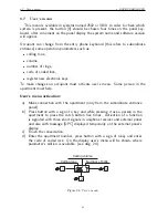
Страница 22: ...in the holes and fix the base on the wall with screws Then connect cables in accordance with connection scheme and screw down the cover Module MRL 1 does not require feeding or any configuration or adjustment 6 7 Assembly of CVP 2 commutator Commutator should be mounted in the installation box or in the wall inside the building preferably in the installation box together with electronic cassette a...

Страница 23: ... 2 dB 4 dB 136 100 124 100 136 124 On Off Figure 12 Configuration of CVP 2 commutator 6 8 Installation of distributor CVR 1 and CVR 2 Floor distributors CRV x should be installed in staircases in which video entry phone is installed Distributor is fastened to the wall by two screws Four screws should be driven to mount the casing cover to its base After taking off the cover make openings in the ba...

Страница 24: ... 124 lub 136 Ω between terminals C C This resistance should be switched only in one distributor which was installed at the end of line C C If distortion is visible on the screen or the picture is not clear or pale amplifying and signal correction should be switched on For MON1 and MON2 outputs correction and amplification are switched by jumpers in joint J2 while for output MON3 and MON4 by jumper...

Страница 25: ...0 should not be programmed removal of all jumpers On uniphone plate are marked digits assigned to consecutive positions on the joint Example in order to program number 37 jumpers should be put on interfaces in positions 1 4 32 1 4 32 37 Then wires should be connected to uniphone terminals paying attention to their appropriate polarization and the uniphone casing should be closed Uniphone is ready ...

Страница 26: ... be performed individually for each slave electronic cassette In the case of the system with the main entrance at first adjustments in all slave cassettes of the system should be made Next the main cassette should be connected and adjustments should be performed in the same way like in case of balance adjustment for uniphones line considering slave electronic cassettes as uniphones Sequence of ope...

Страница 27: ... informing about installation proce dure Message U informs that installation procedure operates and occupants can use the entry phone Message LOC informs that there is no possibility of entry phone use Install uniphone or monitor in the apartment and connect wires of electric system to it Line L L is protected against short circuit however short circuits of wires especially those which supply moni...

Страница 28: ...tte should be entered The code can be read from a label placed on cassette bottom on the exchange processor or sheet with the codes of the combination lock If administrator key has been defined earlier key can be applied to the reader instead of entering the code ENTER SUCCESSIVELY 4 DIGITS OF CODE 1 2 3 4 OR Figure 17 Entering programming mode If installing specialist s code serial number of elec...

Страница 29: ...CODE 0 1 2 3 4 1 C Panels of doorphone systems CD 3100 are protected against theft by means of PIN codes In order to use the panel the PIN code supplied along with the panel by company Laskomex should be introduced only once This operation should be also accomplished after each replacement of electronic cassette or after changing of physical number in the outer panel Start procedure P 0 On the dis...

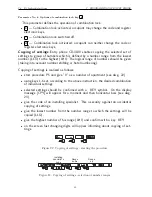
Страница 30: ...er operated in H mode results in the loss of some information including recorded in memory numbers of electronic That s why this function should be used carefully After the change of cassette type the operation of restoring default settings and erasing the electronic s key memory should be made see page 47 tOc 10 255 30 U H Waiting time for picking up the receiver in seconds Parameter defines wait...

Страница 31: ...ation in ms parameter value x 10ms F1 50 255 125 U H Signal frequency F1 in Hz parameter value x 10 Hz F2 50 255 175 U H Signal frequency F2 in Hz parameter value x 10 Hz Electro catch trY 1 31 5 U H Time of electro catch operation Kind of numbering nbl 0 9998 0 U Block number Value above 0 is set in electronic cassette servicing subordinate entrance switches on mode with building numbering This m...

Страница 32: ...e directed to uniphone number given as LdP value see item 4 page 10 Ld1 0 9998 0 U Additional number not included in the serviced range Additional number not included in the serviced range Number introduced as a value of this parameter will be assigned as a logical number of uniphone of physical number 251 Ld2 0 9998 0 U Additional number not included in the serviced range Additional number not in...

Страница 33: ...rs regardless of setting for the individual apartments CoEd 1 U Permission to edition of coded lock codes by occupants By default the occupants have the possibility to change the codes of a combination lock in user s menu Setting this parameter to value 0 blocks this possibility to all occupants regardless of individual settings CoPo 1 U Permission to confirm the use of lock code Each unblocking o...

Страница 34: ...nd the second time at the subordinate entrance see page 43 nrbl 1 H Mode with building numbering Switches on the mode with the building numbering The function will operate properly if parameter nbl in U exchanges is above zero 7 4 P 3 Installation procedure 3 SWITCH ON THE INSTALLATION PROCEDURE 0 C The procedure facilitates the activation of an entry phone system Starting pro cedure P3 enables th...

Страница 35: ...inciple of operation is similar to procedure P 3 5 In order to calculate the logical number of a uniphone its physical number should be entered from a keyboard and then it should be confirmed by a key with a symbol of key P 3 7 SYSt Restoring the default parameters of the exchange operation defined by procedures P 1 and P 2 P 3 8 CodL Restoring the default parameters of the values of the coded loc...

Страница 36: ...ell in which key number was saved If the key has already been saved in entry phone memory a message OLD will appear on the display An installing specialists cannot change the item in which key number is saved The key is registered in the next free mem ory item An installing specialist can make a list in which key position in memory as well as the name of a person to which the key will be given It ...

Страница 37: ...ells in which the keys are saved are protected against recording in other way To reset special key or service key procedure P 4 6 should be used Key organization in memory is as follows Operation mode EC 3100 U EC 3100 H Regular keys 0 999 0 1999 Special keys 1000 1019 2000 2039 Administrator s keys 1020 1023 2040 2047 Registration of keys is as follows Start procedure P 4 3 On the display message...

Страница 38: ...y KEY to pass to the next item If in the next few seconds none key is used the entry phone will search automatically the next key attributed to the selected apartment number As soon as the whole base is searched message End will be displayed End P 4 6 PdEl U Resetting key recorded in the defined item Procedure is used for key resetting after having given the memory item in which 4 6 CELL NUMBER IN...

Страница 39: ...h procedure P 4 6 7 6 P 5 Individual settings In system CD 3100 there is a possibility of individual settings of some parameters of entry phone connected with uniphone calling and functions of combination lock Values of parameters 1 3 may be changed by occupants by user s menu see page 45 parameters 4 6 are available for the installing specialist only Parameter values 5 1 2 Figure 20 Starting the ...

Страница 40: ...phone Uniphone may be called conversation can be conducted and electro catch may be controlled Uniphone switched off Selection of this option makes that it is impossible to make a connection with the apartment for which such setting was selected An attempt to make a connection will be followed by a message OFF d Uniphone functions as a bell Uniphone may be called however conver sation cannot be co...

Страница 41: ...ying of settings is realized as follows start procedure P5 and give 0 as a number of apartment see dwg 22 using keys 1 6 set according to the above instruction the desired combination of individual settings selected settings should be confirmed with a KEY symbol On the display message CPY will appear for a moment and then horizontal bars see dwg 23 give the code of an installing specialist This a ...

Страница 42: ...causes switching on the electro catch for the set time and then return to the program main menu 7 9 P 8 Release of electro catch in service mode 8 This procedure enables the installing specialist to enter the staircase e g to service the installation Owing to this he does not have to ask for opening the door by the occupants Activation of this procedure makes that the door is unblocked and then th...

Страница 43: ...sec Release of the entrance lock is signaled with acoustic signal from loudspeaker in external panel In selected apartments an installing specialist may switch off the possibility of activating the electro catch or limit it to the activation of electro catch at the main or subordinate entrance In entry phones with more than one entrance users may see a message ZAJ This message means that a convers...

Страница 44: ...nce the entrance should be unblocked by pressing the electro catch pushbutton in uniphone or monitor Then uniphone forks should be pressed for a while activation of a function will be confirmed by three increasing sounds in the uniphone receiver The function can be switched off by pressing uniphone forks for the second time Switching off the function will be confirmed by three decreasing sounds in...

Страница 45: ... with lock code is as follows Enter from the keyboard the number of apartment and confirm by a key KEY Enter four digit code After having given the correct code the electro catch will be released In the uni phone in an apartment whose code was used to open the door three short acoustic signals will be generated to inform the occupants that somebody has used their code Each failed attempt to enter ...

Страница 46: ...er s menu Some person in the apartment must help User s menu activation a Make connection with the apartment only from the subordinate entrance panel b Press button with a sign of a key and while pressing it ask a person in the apartment to press the catch button five times Activation of a function is signaled with three short signals in uniphone receiver and external panel and also with message O...

Страница 47: ...ging the code by the user can be blocked by an installing specialist Registering of a new electronic key In user s menu after selecting 8 message ADD will appear on the display Elec tronic key should be put to the reader Message NEU means that key was recorded in memory and attributed to the apartment If a key which was recorded earlier is put to a reader on the display message OLD will appear Exi...

Страница 48: ...Operation mode of electronic cassette will not be changed i e if before restoring default settings the cassette was configured as EC 3100 H after finishing of this operation the cassette will still operate in this mode Pushbutton RESET is used for momentary stopping the operation of a processor Its pressing makes that the processor stops working while the release causes the op eration resumption t...

Страница 49: ... left on it This surface should not be cleaned with sharp objects which can scratch the plate External panels should be cleaned with means which do not contain solvents Uniphones should be cleaned with a damp cloth or using the means for cleaning plastics It is forbidden to use solvents In case the monitor gets dirty it should be cleaned with a soft and damp cloth It is recommended to do it with p...

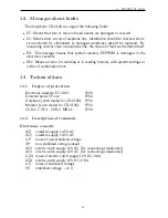
Страница 50: ...r in reading memory with system settings or codes of combination lock 13 Technical data 13 1 Degree of protection Electronic cassette EC 3100 IP20 External panel CP xxx IP44 Uniphone each model for CD 3100 IP30 Monitor each model for CD 3100 IP30 CVR 1 CVP 1 CVR 2 MRL 1 IP30 13 2 Description of terminals Electronic cassette AC1 cassette supply 14 5V AC AC2 cassette supply 14 5V AC GP mass of non s...

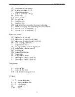
Страница 51: ...connection of accumulator External panel XZ electro catch output GZ electro catch supply input mass VZ electro catch supply input 12V DC PR door opening pushbutton T digital transmission VS el supply of the cassette digital part GD digital mass display system MC microphone MG mass of microphone SP loudspeaker SG mass of loudspeaker C video signal output symetric C video signal output symetric Unip...

Страница 52: ...ine L line L L line L X X vision signal output Y Y vision signal output C1 C1 video input C2 C2 video input C3 C3 video input not included into CVP 1 C4 C4 video input not included into CVP 1 Electronic cassette power supply ZS K 25 01 or TSZZM 25 021M wires description USEC1 USEC2 USEC3 UPRI brown blue brown white red UPRI 230V USEC1 12 5V 0 8A USEC1 USEC2 14 5V 0 8A USEC3 12V 1A brown brown 51 ...

Страница 53: ...NTS 14 Dimensions of elements 4 screws fixing casing of the exchange to its base Figure 26 Dimensions of electronic cassette EC 3100 34 82 132 Figure 27 Dimensions of distributor CVR 1 CVR 2 switch CVP 2 and MRL 1 module 52 ...

Страница 54: ...14 DIMENSIONS OF ELEMENTS Figure 28 Dimensions of panels CP 3100xx with a frame for mounting under plaster 53 ...

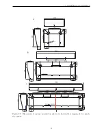
Страница 55: ...14 DIMENSIONS OF ELEMENTS Figure 29 Dimensions of casings mounted on plaster in horizontal arrangement for panels CP 3100xx 54 ...

Страница 56: ...14 DIMENSIONS OF ELEMENTS Figure 30 Dimensions of casings mounted on plaster in vertical arrangement for panels CP 3100xx 55 ...

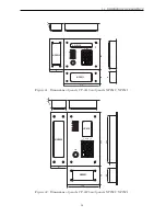
Страница 57: ...4 186 34 156 64 68 180 CP 3110 NP2511 NP2512 2 5 Figure 31 Dimensions of panels CP 3110 and panels NP2512 NP2511 160 244 81 266 88 NP2521 NP2522 64 136 34 2 5 64 CP 3120 Figure 32 Dimensions of panels CP 3120 and panels NP2522 NP2521 56 ...

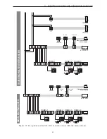
Страница 58: ...tance Clamps 15m 15V GND 1mm 2 Distance U E Clamps 50m 150m L L 0 5mm 2x0 5mm C C 0 5mm Distance CVR M Clamps 30m L L C C 0 5mm Distance CVR M Clamps 15m 30m L L C C 0 5mm 15V GND 0 5mm 2x0 5mm Distance CVR M Clamps 30m L L C C 0 5mm VC GV GC 0 5mm 6 6 4 4 DISTRIBUTION CABINET U M M any YTKSY UTP YTKSY UTP YTKSY UTP YTKSY UTP LAN T11 XzTKMXpw 12 8 8 8 2 3x Cx Cx 6 6 CS V VS G GS L L LM 2 connectio...

Страница 59: ...e H U Clamps 15m 50m 150m 250m L L 0 5mm 2x0 5mm 3x0 5mm C4 C4 0 5mm MRL 1 CVP 2 EC 3100 H 4 4 8 MC GA SP T GS VS KZ VZA GZ GZA 5 CS V VS G GS L L 6 8 8 12 2 2 DISTRIBUTION CABINET H every connection inside the distribution cabinet make by 0 5mm YTKSY or UTP wires unless it is otherwise marked any any any 2 2 GD PR Clamps Distance CP MRL 1 15m 50m SG SP GAx SPx MG MC GAx MCx 0 5mm GD T GSx Tx C C ...

Страница 60: ...3100 H MRL 1 EC 3100 U Distance U E Clamps 50m 150m L L 0 5mm 2x0 5mm 2 4 8 MC GA SP T GS VS KZ VZA GZ GZA 6 10 2 2 DISTRIBUTION CABINET H DISTRIBUTION CABINET U any any any 2 2 GD PR Clamps Distance CP MRL 1 15m 50m SG SP GAx SPx MG MC GAx MCx 0 5mm GD T GSx Tx GD VS GSx VSx 0 5mm 2x0 5mm VZ GZ KZx GZx 6 6 2 OPTION 10 6 6 8 2 E the furthest uniphone B B 2x0 5mm 2 2 2 2 uniphone LG 8d LG 8d Distan...

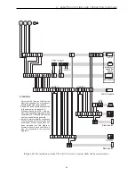
Страница 61: ...rom local feeders Panels Nr 3 and 4 should be connected in the same way as panel Nr 2 Electronic cassette MRL 1 module feeder ZS K 25 01 art 0018 and commutator CVP 2 should be mounted as close each other as possible In order to improve legibility connection of list of occupants accumulator and push button of door opening has not been included into this diagram Elements should be connected in a wa...

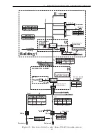
Страница 62: ... AC 0 8 A 12 V AC 1 A MRL 1 White Brown L L MC GA SP T GS VS AC4 AC3 AC2 AC1 Brown Brown GA MC SP GS T VS KZ GZ PANEL 1 T1 MC1 SP1 GA1 GS1 T2 MC2 SP2 GA2 GS2 T3 MC3 SP3 GA3 GS3 PANEL 2 PANEL 3 LM L L L L MAIN ENTRANCES SUBORDINATE ENTRANCES Uniphone Uniphone CP 31xx CP 31xx CP 31xx CP 31xx CP 31xx CP 31xx CP 31xx VZA GZA VZA GZA KZ1 VS1 GZ1 KZ1 VS1 GZ1 Electronic cassette power supply Electronic c...

Страница 63: ... MON 2 MON 1 Electronic cassette power supply 230V C C Figure 38 Doorphone system CD 3100 in video version monitor feeder PLUG RJ 45 UTP NOTE in every monitor connected to distributor CVR 1 jumper Z1 should be in position UTP TERM in distributor at the end of C C line set JP1 to the one of three possible value This value should be selected experimentally to get the best picture on monitor screens ...

Страница 64: ...tem CD 3100 video Connection of monitors using CVR 2 distributor central power supply of monitors Electronic cassette EC3100 230V AC 50Hz Powe supply 13 5V DC 1A CVR 2 IN MVC 6x50 MON4 MON1 NC1 L L NC2 230V AC 50Hz VC Local power supply 13 5V DC 1A B1 C C GB GND 15V AUD CC GC GS VS 1C L L 1C L L GND 15V C L L C AC AC C C AC AC Figure 41 System CD 3100 video Connection of monitors using CVR 2 distr...

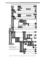
Страница 65: ... Y Y C C L L T T C1 C1 GZ1 230V C1 C1 ATTENTION Only panel Nr 1 can be fed from the electronic cassette The other panels should be fed from local feeders Panels Nr 3 and 4 should be connected in the same way as panel Nr 2 Electronic cassette MRL 1 module electronic cassette power supply and commutator CVP 2 should be mounted as close each other as possible In order to improve legibility connection...

Страница 66: ...TTENTION Clamps C C should be connected with clamps marked as X X 8 brown 4 blue 5 blue white 2 orange white 1 orange 7 brown white PANEL 2 MC2 GA2 SP2 T2 GS2 8 brown 4 blue 5 blue white 2 orange white 1 orange 7 brown white 8 brown 4 blue 5 blue white 2 orange white 1 orange 7 brown white 8 brown 4 blue 5 blue white 2 orange white 1 orange 7 brown white 230V Electro catch CP 31xx Electronic casse...

Страница 67: ... 1 MC MG SG SP T GD VS C C VZ GZ MC1 GA1 SP1 T1 GS1 VS1 C1 C1 KZ1 GZ1 CP 31xx Electro catch XZ to the next distributors L L T T C C Connection with the main entrance 13 5 V DC 1A CVR 1 CP 31xx 230 VAC White Brown AC4 AC3 AC2 AC1 Brown Brown 14 5 V AC 0 8 A 12 V AC 1 A C3 C3 MC3 GA3 SP3 T3 GS3 To the next slave entrances L L C C GV VC ST C2 VZ VZ blue 4 blue white 5 brown white 7 brown 8 green whit...

Страница 68: ...on points shops places appointed by the producer or commune waste collection units INSTRUCTION ON ENVIRONMENT PROTECTION List of collecting units of used Laskomex equipment is available on www laskomex com pl website or telephone No 42 671 88 68 Product packing should be removed according to environment protection regulations Remember Selective collection and recycling of used electronic and elect...

Отзывы: